Antenna assembly and electronic device using same

An antenna assembly and electronic device technology, which is applied to antenna supports/installation devices, antenna parts, antennas, etc., can solve the problems of high manufacturing cost, wrinkling of the outer shell 91, increase in the cost of wireless communication terminals, etc., and saves welding. Process and cost reduction effect

Inactive Publication Date: 2010-06-09
FUTAIJING PRECISION ELECTRONICS BEIJING
View PDF3 Cites 1 Cited by
  • Summary
  • Abstract
  • Description
  • Claims
  • Application Information

AI Technical Summary

Problems solved by technology

[0003] However, when the conductive terminal 94 is welded on the antenna layer 92, the production cost is relatively high, and at the same time, it is easy to cause the shell layer 91 to wrinkle near the welding point, thereby affecting the appearance of the wireless communication terminal.
In addition, when forming the inner shell layer 93, in order to ensure that the conductive terminal 94 can be in conductive contact with the elastic guide post 95, a precisely designed mold structure is required, which will also increase the cost of the wireless communication terminal.

Method used


Image

  • Antenna assembly and electronic device using same
  • Antenna assembly and electronic device using same
  • Antenna assembly and electronic device using same

Examples


Embodiment Construction

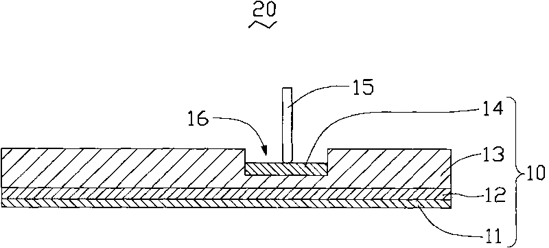
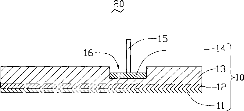
[0011] see figure 2 , the antenna assembly 10 of the preferred embodiment of the present invention includes a bearing layer 11 , an antenna layer 12 , a base layer 13 and a resonant coupling body 14 .

[0012] The carrier layer 11 can be a decorative resin film, such as polycarbonate, acrylonitrile-butadiene-styrene copolymer (Acrylonitrile-Butadiene-Styrene, ABS), polystyrene (PS, Polystyrene) or polyvinyl chloride ( PVC, Poly Vinyl Chloride) and other resin films.

[0013] The antenna layer 12 is a conductive pattern for receiving and sending radio signals. The antenna layer 12 may be a conductive ink layer formed on the carrying layer 11 by printing. The antenna layer 12 can also be a metal foil, such as copper foil, which can be attached to the carrier layer 11 by an adhesive. In addition, the antenna layer 12 can also be a metal coating layer formed as a conductive pattern, and the metal coating layer can be a vacuum coating layer or an electroplating layer.

[0014]...


PUM


Abstract

The invention relates to an antenna assembly which comprises a bearing layer, a basal body layer, an antenna layer and a resonant coupling body, wherein the antenna layer is clamped between the bearing layer and the basal body layer, the resonant coupling body is attached onto the basal body layer and is resonantly coupled with the antenna layer, and the antenna layer and the resonant coupling body are spaced through the basal body layer. The invention also provides an electronic device using the antenna assembly.

Description

technical field [0001] The invention relates to an antenna component and an electronic device using the antenna component. Background technique [0002] Antennas for wireless communication terminals mainly include built-in antennas and external antennas. Compared with an external antenna, a built-in antenna can effectively reduce the size of a wireless communication terminal. Therefore, currently, a wireless communication terminal generally adopts a design of a built-in antenna. Please refer to figure 1 , the existing wireless communication terminal designed with a built-in antenna includes a shell layer 91, an antenna layer 92, an inner shell layer 93, a conductive terminal 94, a circuit board (not shown) and connected to the circuit board An elastic guide post 95. The shell layer 91 is usually a decorative plastic film for carrying the antenna layer 92 . The antenna layer 92 is formed on or attached to the outer shell layer 91 , and is sandwiched between the outer shel...

Claims


Application Information

Patent Timeline
Patent Type & Authority Applications(China)
IPC IPC(8): H01Q1/24H01Q1/38H01Q3/24
CPCH01Q1/243H01Q1/38
Inventor 李展
Owner FUTAIJING PRECISION ELECTRONICS BEIJING
Why Eureka
Try Eureka