Sound intensity testing bracket

A technology of sound intensity and sound intensity probe, which is used in measuring devices, measuring ultrasonic/sonic/infrasonic waves, instruments, etc., can solve problems such as hearing damage, danger, and loud engine noise, and achieve easy popularization, simple operation and low cost. Effect

Active Publication Date: 2012-06-27
CHERY AUTOMOBILE CO LTD
View PDF0 Cites 1 Cited by
  • Summary
  • Abstract
  • Description
  • Claims
  • Application Information

AI Technical Summary

Problems solved by technology

[0002] It is very inconvenient to hold the sound intensity probe in the automotive industry to test the sound intensity
And when testing the sound intensity of the engine, the noise near the high-speed engine is very loud, causing hearing damage to people, and it is also very dangerous to test near the high-speed engine

Method used


Image

  • Sound intensity testing bracket
  • Sound intensity testing bracket
  • Sound intensity testing bracket

Examples


Embodiment Construction

[0025] The present invention will be described in detail below according to the accompanying drawings, which is a preferred embodiment of the various embodiments of the present invention.

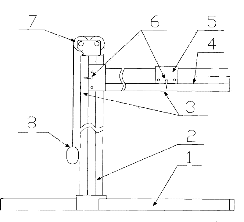
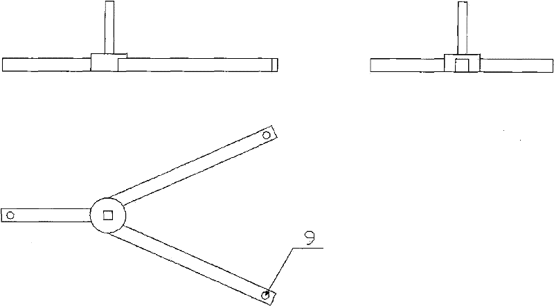
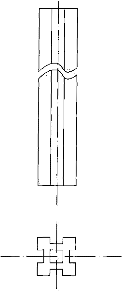
[0026] The operation method of the present invention: place the bracket base 1 on the position of the sound intensity to be measured, insert the vertical rail 2 into the bracket base 1, and fix it; slide the horizontal rail 4 into the rail from the top of the vertical rail 2; insert the pulley group 7 into the vertical rail The top of the track 2 is fixed; after the balance weight and the rope 8 are connected to the hanging hole of the traction rope to 13, they bypass the pulley block, and adjust the bracket base 1 to be horizontal through the vertical condition of 8 and the horizontal plane; after adjusting the level, put the horizontal trolley 5 Slide into the track from the outside of the horizontal track 4, and fix the sound intensity probe to the horizontal trolley 5. The sound intensi...


PUM


Abstract

The invention relates to a sound intensity testing bracket, which comprises a bracket base, a vertical rail, a horizontal rail and a sound intensity probe, wherein the vertical rail is vertically arranged on the bracket base; the horizontal rail is vertically arranged on the vertical rail and is arranged horizontally; and the sound intensity probe is movably arranged on the horizontal rail.

Description

technical field [0001] The invention relates to the NVH test belonging to the automobile industry, in particular to a sound intensity test bracket, which can complete the sound intensity test when the sound intensity cannot be measured with a hand-held sound intensity probe. Background technique [0002] When testing sound intensity in the automotive industry, it is very inconvenient to hold a sound intensity probe. And when testing the sound intensity of the engine, the noise near the high-speed engine is very loud, causing damage to people's hearing. In addition, it is very dangerous to test near the high-speed engine. SUMMARY OF THE INVENTION [0003] In view of the above inconvenience, the purpose of the present invention is to provide a sound intensity test stand, so that the tester can complete the sound intensity test away from the engine or the dangerous test position. [0004] Specifically, the purpose of the present invention is to provide a two-dimensional plan...

Claims


Application Information

Patent Timeline
Patent Type & Authority Patents(China)
IPC IPC(8): G01H17/00
Inventor 刘文强
Owner CHERY AUTOMOBILE CO LTD
Why Eureka
Try Eureka