Rapid locking cable clamp

A fast and locking technology, applied in the fields of power equipment, circuit equipment and hardware, can solve the problems of difficulty and inconvenience of automatic installation, and achieve the effect of simple and feasible construction, reasonable structure and simple operation.

Inactive Publication Date: 2012-04-11
孙渭清
View PDF0 Cites 1 Cited by
  • Summary
  • Abstract
  • Description
  • Claims
  • Application Information

AI Technical Summary

Problems solved by technology

[0002] At present, wire spacer rods, ground wire damping wire clamps, anti-vibration hammers and anti-shielding lightning rods widely used on power lines mostly use plug-in locking pins and cotter pins or plug-in locking pins plus rotation operations. It usually takes three to four actions to lock the clamp, which is very inconvenient, especially for live work on overhead lines, which causes great difficulties for automatic installation.

Method used


Image

  • Rapid locking cable clamp
  • Rapid locking cable clamp
  • Rapid locking cable clamp

Examples


Embodiment Construction

[0024] The present invention will be further described below in conjunction with the accompanying drawings and embodiments.

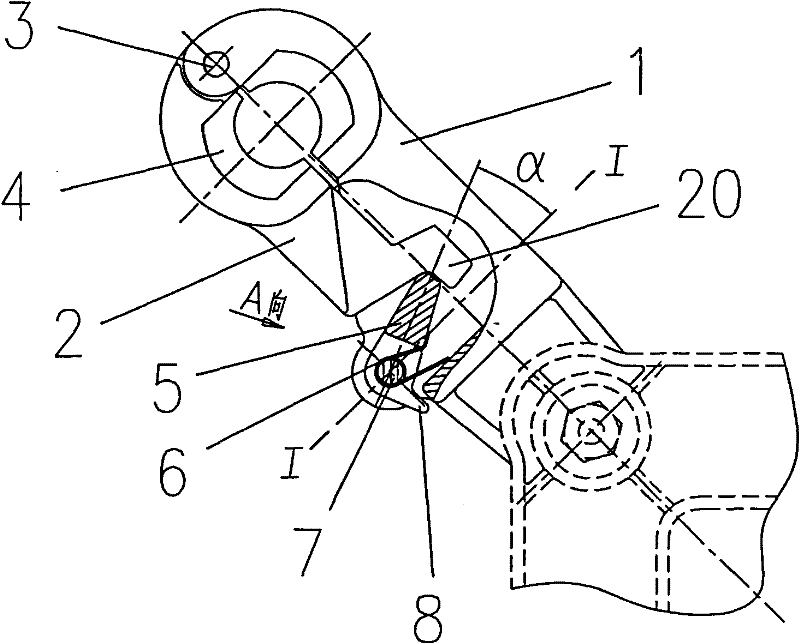
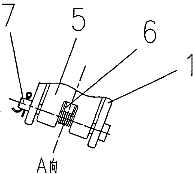
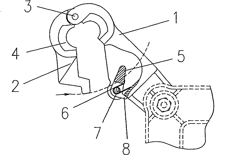
[0025] Such as figure 1 , figure 2 , a quick locking wire clamp for power lines, which is composed of a wire clamp body 1, a cover plate 2, a hinge shaft 3, a lock tongue 5, a spring 6, a pin shaft 7 and a limiter 8, and the wire clamp The body 1 and the cover plate 2 are connected by the hinge shaft 3, the lock tongue 5 is installed on the clamp body 1 by the pin shaft 7, and the spring 6 is arranged on the pin shaft 7, and the spring 6 makes the lock tongue 5 rotate counterclockwise around the pin shaft 7. The end of the cover plate 2 is provided with a stop block 20, and the lock tongue 5 is in contact with the stop block 20; the function of the stop block 20 is to make the lock tongue 5 firmly clamp on the cover plate 2, and ensure that it does not displace or shift And cause cover plate 2 to throw off.

[0026] After the cover plate 2 is tight...


PUM


Abstract

The invention discloses a rapid locking cable clamp for an electric power circuit, which is characterized by comprising a cable clamp body, a cover plate, a hinge shaft, a lock tongue spring, a hinge pin and a limiting body, wherein the cable clamp and the cover plate are connected by the hinge shaft, a lock tongue is installed on the cable clamp body through a lock tongue hinge pin on which a spring is arranged, the spring enables the lock tongue to have an anticlockwise torque surrounding the hinge pin, the tail end of the cover plate is provided with a stop block, and the lock tongue is incontact with the stop block; after the cover plate and the cable clamp body are closed tightly, the lock tongue locks the cover plate tightly and is in a self-locking state, and the initial position of the lock tongue before online clamping operation can be limited by the limiting body. The rapid locking cable clamp has simple operation, safety and reliability, can be suitable for live working ofoverheadlines, automatic installation of power equipment and rapid locking of line material and hardware fittings. The invention can simplify the three-four original actions into one action for finishing installation operation, not only ensure the line installation, but also ensure that the construction is simple, convenient and feasible.

Description

technical field [0001] The invention belongs to the field of electric equipment, line equipment and fittings, and in particular relates to a quick-locking clamp applied on electric lines. Background technique [0002] At present, wire spacer rods, ground wire damping wire clamps, anti-vibration hammers and anti-shielding lightning rods widely used on power lines mostly use plug-in locking pins plus cotter pins or plug-in locking pins plus rotation operations. To realize the locking of the wire clamp, it generally takes three to four actions to lock the wire clamp, which is very inconvenient, especially for live work on overhead lines, and the automatic installation causes great difficulties. [0003] Therefore, need badly a kind of novel wire clip to overcome above-mentioned drawback. Contents of the invention [0004] The purpose of the present invention is to overcome the deficiencies of the prior art, to provide a simple operation, safe and reliable, and applicable to ...

Claims


Application Information

Patent Timeline
Patent Type & Authority Patents(China)
IPC IPC(8): H02G7/05H02G7/08
Inventor 孙渭清
Owner 孙渭清
Why Eureka
Try Eureka