
Turnover device

A technology of loading cavity and side plate, which is applied in packaging, transportation and packaging, and packaging of vulnerable items, can solve the problems of the substrate 50` yield drop, substrate 50` scratches, substrate 50` pollution, etc., and achieve cleanliness The effect of reducing the concentration of internal stress and high cleanliness

Inactive Publication Date: 2012-05-02
DONGGUAN ANWELL DIGITAL MASCH CO LTD
View PDF0 Cites 0 Cited by
  • Summary
  • Abstract
  • Description
  • Claims
  • Application Information

AI Technical Summary

Problems solved by technology

[0003] In an existing turnover device for storing and transporting substrates, multiple substrates are placed in the substrate turnover device in an upright manner. The substrate turnover device is placed upright on a horizontal workbench, and multiple substrates are placed upright during operation The substrate is not easy to take out; in the process of transportation, due to vibration, it is easy to cause the substrate to fall
Another type of turnover device is to place the substrate horizontally. As shown in Figure 1, the support part 31' of this turnover device is arranged horizontally. There are two problems in this way: one is that the supporting part 31' is set horizontally, and there is a lot of dust on it. After the substrate 50' is placed on the horizontal plane of the supporting part 31', the dust on the horizontal surface will cause the substrate 50' to be affected. Second, when the size of the substrate 50` is large, the substrate 50` will be slightly deformed due to the effect of gravity, causing the edge of the substrate 50` to warp. The contact surface of the part 31' is reduced, that is, the surface contact before deformation becomes the line contact after deformation. Since the support part 31' is not processed, it is easy to scratch the substrate 50'; Large internal stress concentration causes irregular deformation, which eventually reduces the yield of the substrate 50`, and the substrate 50` is easy to drop during transportation

Method used


Image

  • Turnover device
  • Turnover device
  • Turnover device

Examples


Embodiment Construction

[0032]Embodiments of the present invention will now be described with reference to the drawings, in which like reference numerals represent like elements.

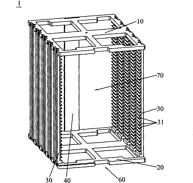
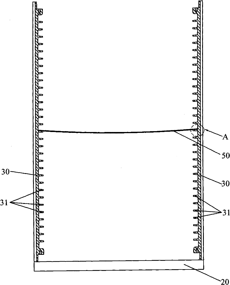
[0033] like Figure 2-Figure 5 As shown, the turnaround device 1 of the present invention is used to carry and transport thin-plate-shaped substrates 50. It includes a top plate 10, a bottom plate 20, a baffle plate 40, and two side plates 30. The top plate 10 and the bottom plate 20 are arranged in parallel, and the two side plates 30 They are arranged parallel to each other between the top plate 10 and the bottom plate 20, the side plates 30 are perpendicular to the top plate 10 and the bottom plate 20, the top plate 10, the bottom plate 20 and the side plates 30 form a substrate loading chamber 70 with two openings, and the baffle plate 40 is arranged on Between the top plate 10 and the bottom plate 20, and the baffle plate 40 is located at one of the two openings and is perpendicular to the two side plates 30, the othe...


PUM


Abstract

The invention discloses a turnover device which comprises a top plate, a bottom plate, a baffle plate and two side plates. The top plate and the bottom plate are arranged in parallel; the two side plates are arranged between the top plate and the bottom plate in parallel and are vertical to the top plate and the bottom plate; the top plate, the bottom plate and the side plates form a base plate loading cavity with two openings; the baffle plate is arranged between the top plate and the bottom plate, is positioned at one of the two openings and is vertical to the side plates; a base plate inlet-outlet for the base plate to pass in and out is formed on the other opening; the side plates are provided with a plurality of supporting bodies extending in a footstep shape towards the base plate loading cavity; an upper supporting face for supporting the base plate is formed on the upper surface of each supporting body and slantwise arranged downwards facing to the direction of the base plate loading cavity; and all face combining parts of the support bodies are circular beads. The turnover device is used for loading and turning over the base plate in OLED production, ensures that the base plate is less polluted and not easily scraped in the turnover process and buffers the centralized action of the internal stress of the base plate, thereby ensuring little deformation of the base plate and improving the rate of good product of the base plate.

Description

technical field [0001] The present invention relates to a turnaround device, in particular to a turnaround device for carrying and turning around a substrate with a preset length in the production of display devices. Background technique [0002] With the development of digital entertainment and multimedia technology, display has become an indispensable part of people's life, such as thin film transistor liquid crystal display (TFT-LCD), due to its light and thin characteristics, in addition to the replacement effect on the existing market , new application fields have also emerged, including portable products, information products and video products; after entering the 21st century, with the increasingly severe international energy situation, consumers' awareness of energy conservation and environmental protection has gradually increased. Therefore, the research and development of low energy consumption and pollution-free green energy-saving technology has become the innova...

Claims


Application Information

Patent Timeline
Patent Type & Authority Patents(China)
IPC IPC(8): B65D85/48B65D81/02B65D6/08B65D25/10
Inventor 杨明生刘惠森范继良郭业祥王曼媛王勇
Owner DONGGUAN ANWELL DIGITAL MASCH CO LTD
Learn More