Stacker crane
A technology of tower crane and guide part, which is applied in the direction of lifting device, storage device, transportation and packaging, etc., can solve the problems such as the reduction of cargo storage efficiency, the shortening of the lifting distance of the lifting part, and the inability to expand the spacing between side rollers.
- Summary
- Abstract
- Description
- Claims
- Application Information
AI Technical Summary
Problems solved by technology
Method used
Image

Examples
no. 1 Embodiment approach
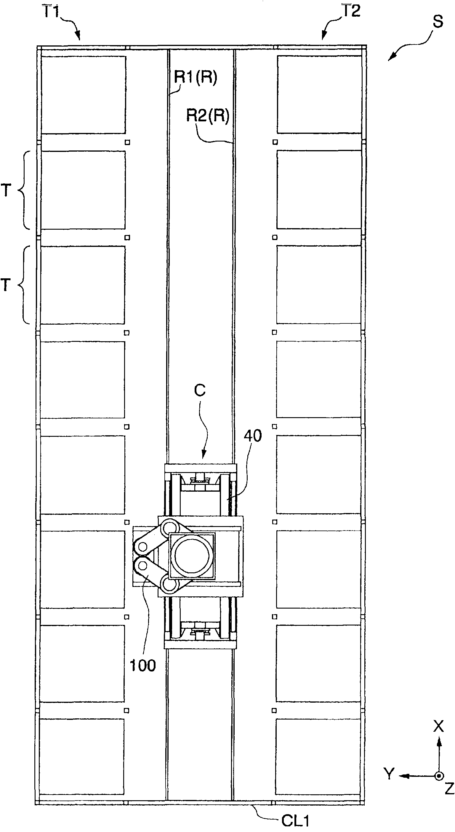
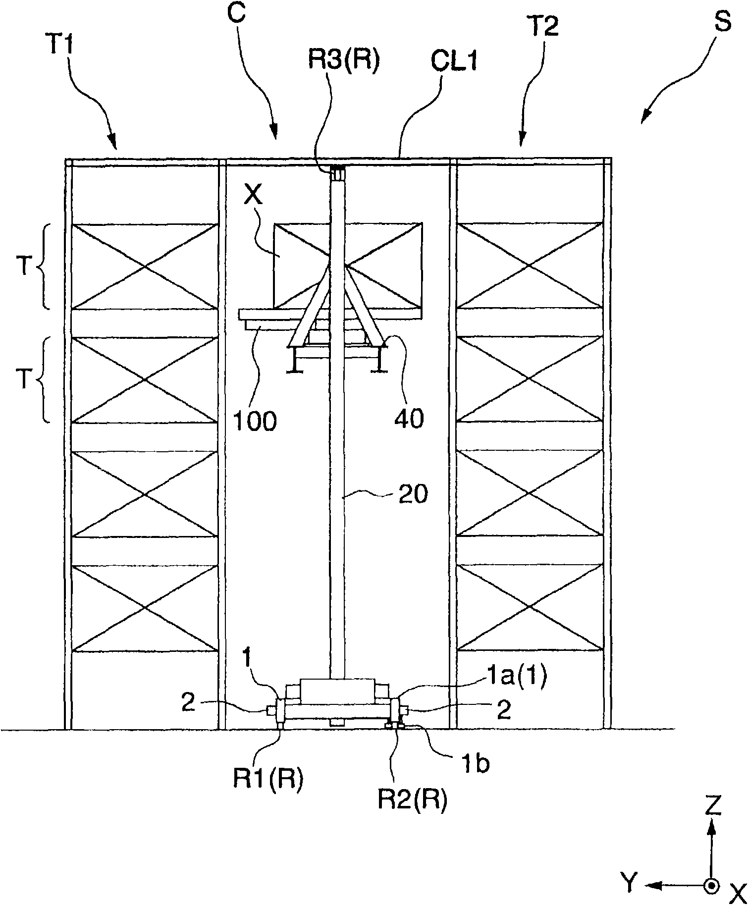
[0040] figure 1 It is a top view of the automatic warehouse S equipped with the tower crane of this embodiment. figure 2 It is a side view of the automatic warehouse S.
[0041] As shown in the figure, the automatic warehouse S includes a tower crane C and racks T1 and T2 arranged opposite to each other across a guide rail R serving as a track for the tower crane C, and the tower crane C transports goods to the racks. Stored on T1 and T2. Furthermore, the automatic warehouse S is equipped with a storage conveyor (not shown) for storing goods in and a delivery conveyor (not shown) for taking goods out of the warehouse, and the tower crane C can Cargo is handed over between the inbound conveyor and the outbound conveyor.
[0042] In addition, in the present embodiment, the cargo is a cargo box X for accommodating a plurality of glass substrates, and the racks T1 and T2 and the tower crane C are arranged in a clean room CL1 with a degree of cleanliness of 10 degrees, for exam...
no. 2 Embodiment approach
[0081] Hereinafter, the second embodiment of the present invention will be described, and in the description of the second embodiment, the description of the same parts as those of the first embodiment will be omitted or simplified.
[0082] Figure 9 It is the perspective view which looked at the state which the lifting frame 40 descended from the downward direction in the tower crane of this embodiment.
[0083] In the above-mentioned first embodiment, the space between the guide part 70a and the guide part 70b is lengthened compared with the prior art, so the side frame 43 itself is made long in the up-down direction.
[0084] And in the tower crane of this embodiment, as Figure 9 As shown, the side frame 43 is not lengthened, but the lower guide portion 70b is configured to protrude downward of the side frame.
[0085] Specifically, the guide part 70b is fixed to the support body 80 extending downward from the side frame 43, the support body 80 is reinforced by the rib ...
no. 3 Embodiment approach
[0089] Hereinafter, a third embodiment of the present invention will be described technically. In addition, in the description of the third embodiment, the description of the same parts as those of the first embodiment or the second embodiment will be omitted or simplified.
[0090] Figure 10It is the perspective view which looked at the state which the lifting frame 40 descended from the downward direction in the tower crane of this embodiment.
[0091] As shown in the figure, in the tower crane according to the present embodiment, the lower guide portion 70b is protrudingly provided below the side frame as in the above-mentioned second embodiment. Moreover, in the tower crane of this embodiment, the lower frame 10 is not formed in a frame shape, but the penetration part 10b through which only the guide part 70b, the support body 80, and the reinforcement rib 90 can pass is formed.
[0092] According to the tower crane of the present embodiment having such a structure, whe...
PUM
 Abstract
Description
Claims
Application Information
 - R&D Engineer
- R&D Manager
- IP Professional
- Industry Leading Data Capabilities
- Powerful AI technology
- Patent DNA Extraction
Browse by: Latest US Patents, China's latest patents, Technical Efficacy Thesaurus, Application Domain, Technology Topic.
© 2024 PatSnap. All rights reserved.Legal|Privacy policy|Modern Slavery Act Transparency Statement|Sitemap