
Powerline remote meter reading repeating method

A technology of remote meter reading and power line, applied in electrical signal transmission systems, signal transmission systems, instruments, etc., can solve the problems of data collision, reducing the available bandwidth of the line, data collision and increase of conflict.

Inactive Publication Date: 2010-03-17
SHANGHAI DIANJI UNIV
View PDF0 Cites 5 Cited by
  • Summary
  • Abstract
  • Description
  • Claims
  • Application Information

AI Technical Summary

Problems solved by technology

The existing technology points out that because the repeater performs power amplification on the transmission signals of all the power line communication devices used within its receiving range, the available bandwidth of the line will be reduced, resulting in a significant increase in the probability of data collisions and collisions
Therefore, the use of repeaters in the existing meter reading system reduces the available bandwidth of the power line, resulting in a significant increase in the probability of data collisions and conflicts

Method used


Image

  • Powerline remote meter reading repeating method
  • Powerline remote meter reading repeating method
  • Powerline remote meter reading repeating method

Examples


Embodiment 1

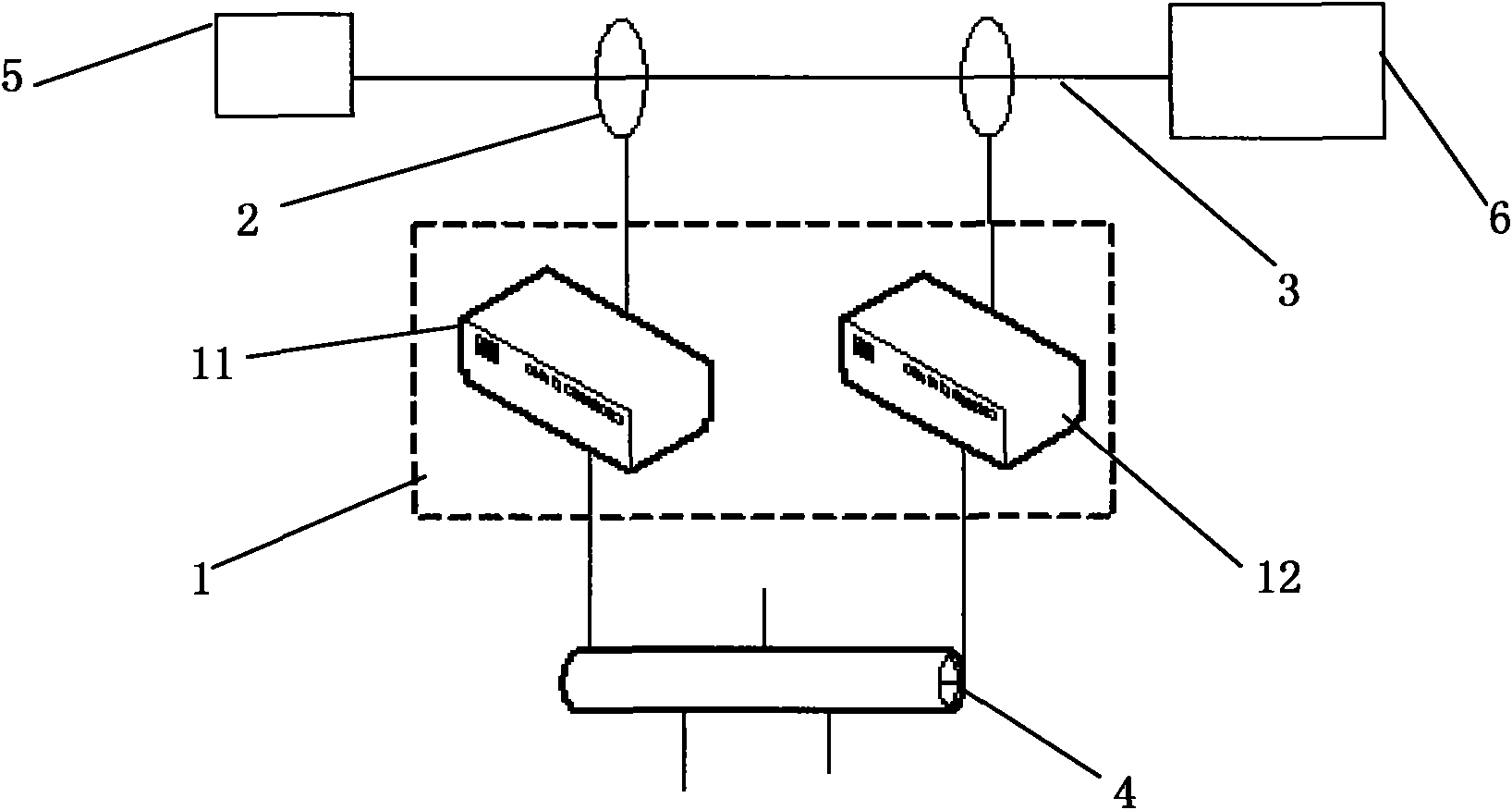
[0026] See figure 2 As shown, the relay method adopted in one embodiment of the present invention needs to be constructed using the structure in the figure. The repeater 1 is composed of a power line communication node 11 and a power line communication node 12. The power line communication node 11 and the power line communication node 12 are arranged in parallel One end of the power line communication node 11 is connected to the power line 3 through the power line coupler 2, the other end of the power line communication node 11 is connected to the Ethernet 4, and the power line communication node 12 is respectively connected to the power line 3 and the Ethernet in the same manner as the power line communication node 11. 4. Wherein, the power line communication node 11 is close to the collector 5 , and the power line communication node 12 is close to the concentrator 6 .

[0027] Described remote relay method comprises the steps:

[0028] Step 1, set the power line communica...

Embodiment 2

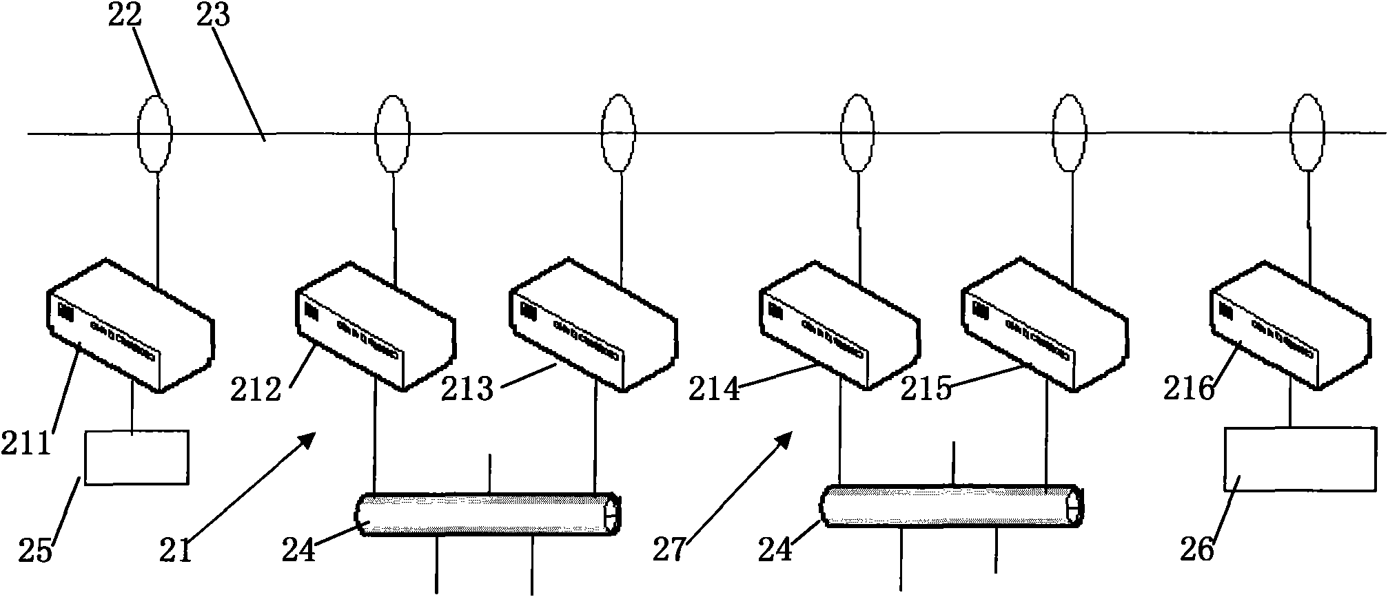
[0033] See image 3 As shown, the relay method used in one embodiment of the present invention needs to be constructed using the structure in the figure. The repeater 21 is composed of a power line communication node 211 and a power line communication node 212. The power line communication node 211 and the power line communication node 212 are arranged in parallel One end of the power line communication node 211 is connected to the power line 23 through the power line coupler 22, the other end of the power line communication node 211 is connected to the Ethernet 24, and the power line communication node 212 is connected to the power line 23 and the Ethernet respectively in the same manner as the power line communication node 211 twenty four. Wherein, the power line communication node 11 is close to the collector 25 , and the power line communication node 12 is close to the concentrator 26 . Repeater 27 is set up in exactly the same way as repeater 21 , repeater 27 comprising ...


PUM


Abstract

The invention provides a powerline remote meter reading repeating method which is as follows: the mode set of a collector and a concentrator in the prior art is not changed, only one or a plurality ofrepeaters are additionally arranged on the powerline according to the actual condition, and wired or wireless network transmission data are adopted in the repeaters. The method can realize the function of data transmission under the condition that the distance between the collector and the concentrator is long, and only carry out data retransmission between the collector and the concentrator witha repeating requirement to increase the network efficiency.

Description

technical field [0001] The invention relates to a data relay method applied in a power line remote meter reading system, more specifically, a data forwarding method for extending the coverage of the power line remote meter reading system. Background technique [0002] Power line communication (power line communication, PLC), also known as power line carrier communication, refers to a unique communication method for power systems. In recent years, power line communication technology, especially broadband over power line communication (BPLC) communication technology refers to a communication technology that utilizes existing power networks to provide high-speed, broadband Internet access for families or businesses. It uses power lines to transmit analog or digital signals through carrier waves. The bandwidth is limited between 2-30MHz, and the communication rate can reach more than 200Mbit / s. Broadband power line communication technology has become a new research hotspot in t...

Claims


Application Information

Patent Timeline
IPC IPC(8): G08C19/00G08C17/02
Inventor 孙强
Owner SHANGHAI DIANJI UNIV
Learn More