
Hydraulic oil cylinder

A technology of hydraulic oil cylinder and cylinder barrel, which is applied to fluid pressure actuating devices, valve details, engine components, etc., can solve problems such as affecting the product qualification rate, smashing the sealing surface of the steam valve, and failing to achieve the closing time of the steam valve. , to achieve the effect of improving production efficiency and product qualification rate

Inactive Publication Date: 2010-03-17
SHANGHAI HUIYI CONTROL SYST
View PDF0 Cites 2 Cited by
  • Summary
  • Abstract
  • Description
  • Claims
  • Application Information

AI Technical Summary

Problems solved by technology

Because the buffer gap of the hydraulic cylinder is difficult to calculate accurately, if the buffer gap is too small, the closing time of the steam valve will not meet the relevant national standards or even exceed the relevant national standards due to too much buffer force when the hydraulic cylinder quickly enters the buffer According to relevant national standards, if the buffer gap is too large, when the hydraulic cylinder enters the buffer zone quickly, the closing force of the steam valve will be too large due to the small buffer force, which will damage the sealing surface of the steam valve.
Therefore, it is often necessary to carry out multiple tests to adjust the buffer gap during processing and manufacturing, which not only affects the production efficiency, but also the adjustment effect is often unsatisfactory, which affects the qualified rate of the product.

Method used


Image

  • Hydraulic oil cylinder
  • Hydraulic oil cylinder

Examples


Embodiment Construction

[0009] The embodiments of the present invention will be described in further detail below in conjunction with the accompanying drawings, but the present embodiments are not intended to limit the present invention, and any similar structures and similar changes of the present invention should be included in the protection scope of the present invention.

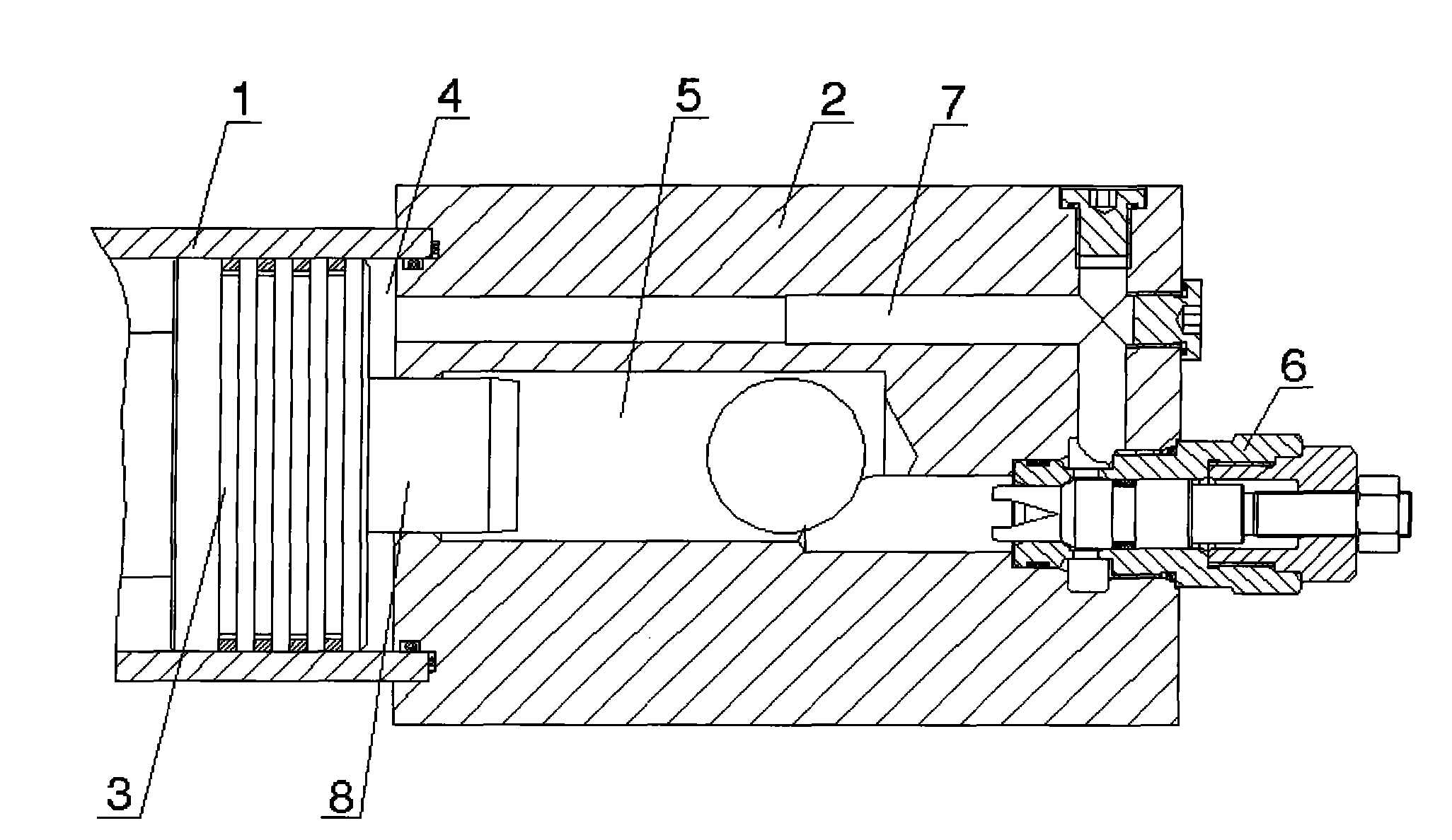
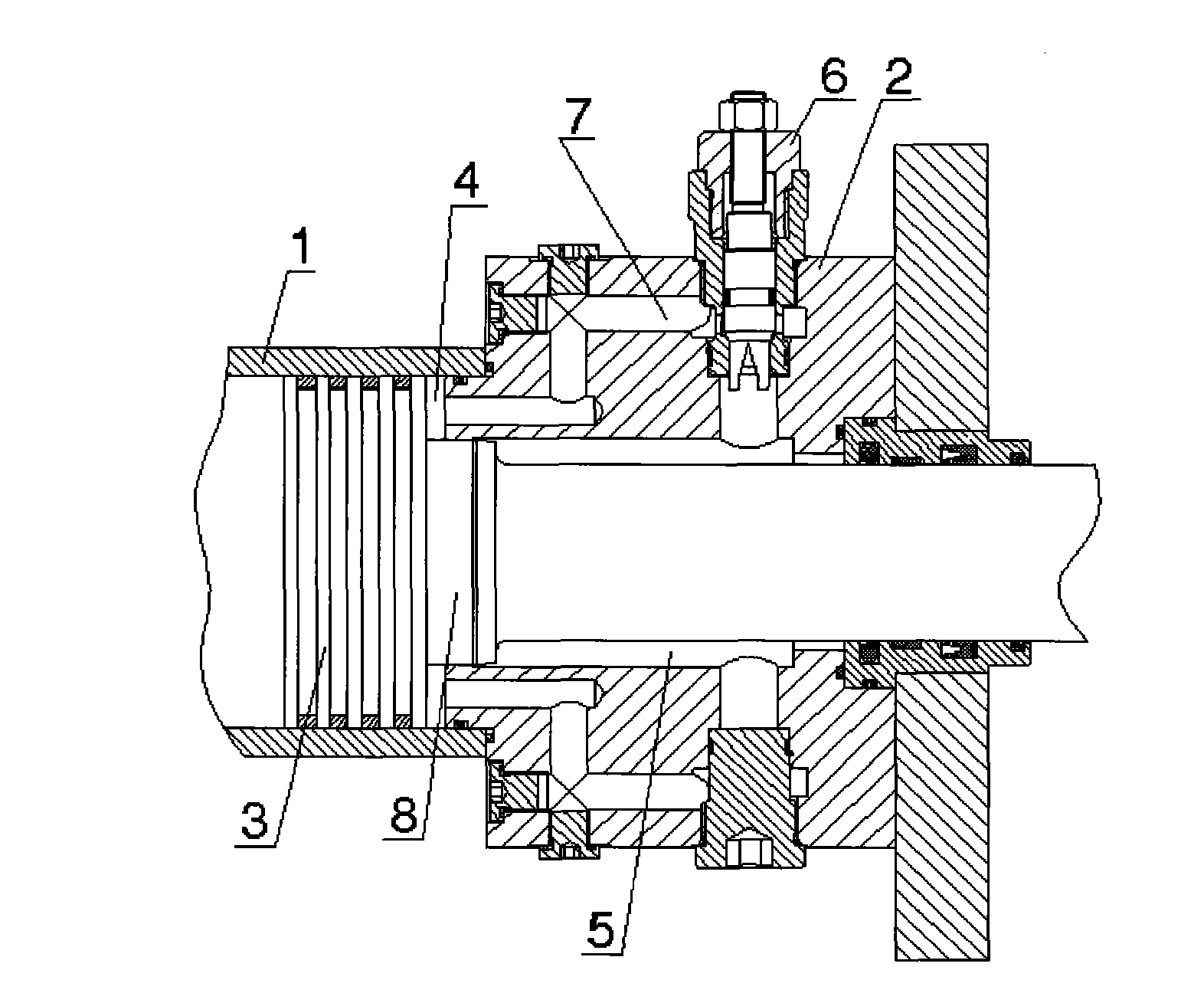
[0010] Such as Figure 1-Figure 2 As shown, a hydraulic cylinder provided by the embodiment of the present invention includes a cylinder 1, end caps 2 at the front and rear ends of the cylinder, and a piston 3 inside the cylinder. The piston 3 separates the cylinder 1 into two chambers at the front and rear Body 4, the end cover 2 corresponding to each cavity 4 is provided with an oil discharge chamber 5 communicating with the cavity 4, and the characteristic is that: the end cover 2 is provided with at least one adjustable buffer valve 6, The end cover 2 where each buffer valve 6 is located is provided with a channel 7 commun...


PUM


Abstract

The invention discloses a hydraulic oil cylinder, which relates to the technical field of hydraulic equipment and solves the technical problems that the prior hydraulic oil cylinder has slow bufferingforce adjustment and poor adjustment effect. The oil cylinder comprises a cylinder barrel, end covers at the front end and the rear end of the cylinder barrel, and a piston in the cylinder barrel, wherein the piston separates the cylinder barrel into a front cavity and a rear cavity, and the end cover corresponding to each cavity is provided with an oil discharge cavity communicated with the cavity. The hydraulic oil cylinder is characterized in that the end cover is provided with at least one adjustable buffer valve, the end cover where each buffer valve is positioned is provided with a passage for communicating the cavity corresponding to the end cover and an oil inlet of the buffer valve, and an oil discharge port of the buffer valve is communicated with the oil discharge cavity of theend cover. The hydraulic oil cylinder provided by the invention can quickly and accurately adjust the buffering force so as to improve the production efficiency and the product percent of pass.

Description

technical field [0001] The invention relates to hydraulic equipment technology, in particular to a technology for driving a hydraulic oil cylinder for opening and closing a steam valve. Background technique [0002] The opening and closing of steam turbine steam valves are all driven by hydraulic cylinders. Because the buffer gap of the hydraulic cylinder is difficult to calculate accurately, if the buffer gap is too small, the closing time of the steam valve will not meet the relevant national standards or even exceed the relevant national standards due to too much buffer force when the hydraulic cylinder quickly enters the buffer According to the relevant national standards, if the buffer gap is too large, when the hydraulic cylinder enters the buffer zone quickly, the closing force of the steam valve will be too large due to the small buffer force, which will damage the sealing surface of the steam valve. Therefore often will carry out many tests to adjust its buffer gap...

Claims


Application Information

Patent Timeline
Patent Type & Authority Applications(China)
IPC IPC(8): F15B15/20F15B15/14F16K31/12
Inventor 阳胜军吴涛
Owner SHANGHAI HUIYI CONTROL SYST
Learn More