
Upper cover structure of post articulated printer with paper tearing function

A printer, hinged technology, applied in the direction of printing device, printing, etc., can solve the problem of tearing difficulty, etc., to achieve the effect of tearing paper more effectively and neatly

Inactive Publication Date: 2010-03-17
KONG YUE ELECTRONICS & INFORMATION IND XIN HUI
View PDF0 Cites 7 Cited by
  • Summary
  • Abstract
  • Description
  • Claims
  • Application Information

AI Technical Summary

Problems solved by technology

[0002] At present, the upper cover of traditional printers is usually covered on the print head, which mainly plays a dust-proof function, but some printers use the upper cover as a tearing blade at the same time, but because the upper cover is hinged on the front of the printer, so When tearing continuous paper, the upper cover is usually lifted, which leads to tearing difficulties, so the development of a more efficient and tidy upper cover structure for tearing continuous paper has been put on people's research agenda

Method used


Image

  • Upper cover structure of post articulated printer with paper tearing function
  • Upper cover structure of post articulated printer with paper tearing function
  • Upper cover structure of post articulated printer with paper tearing function

Examples


Embodiment Construction

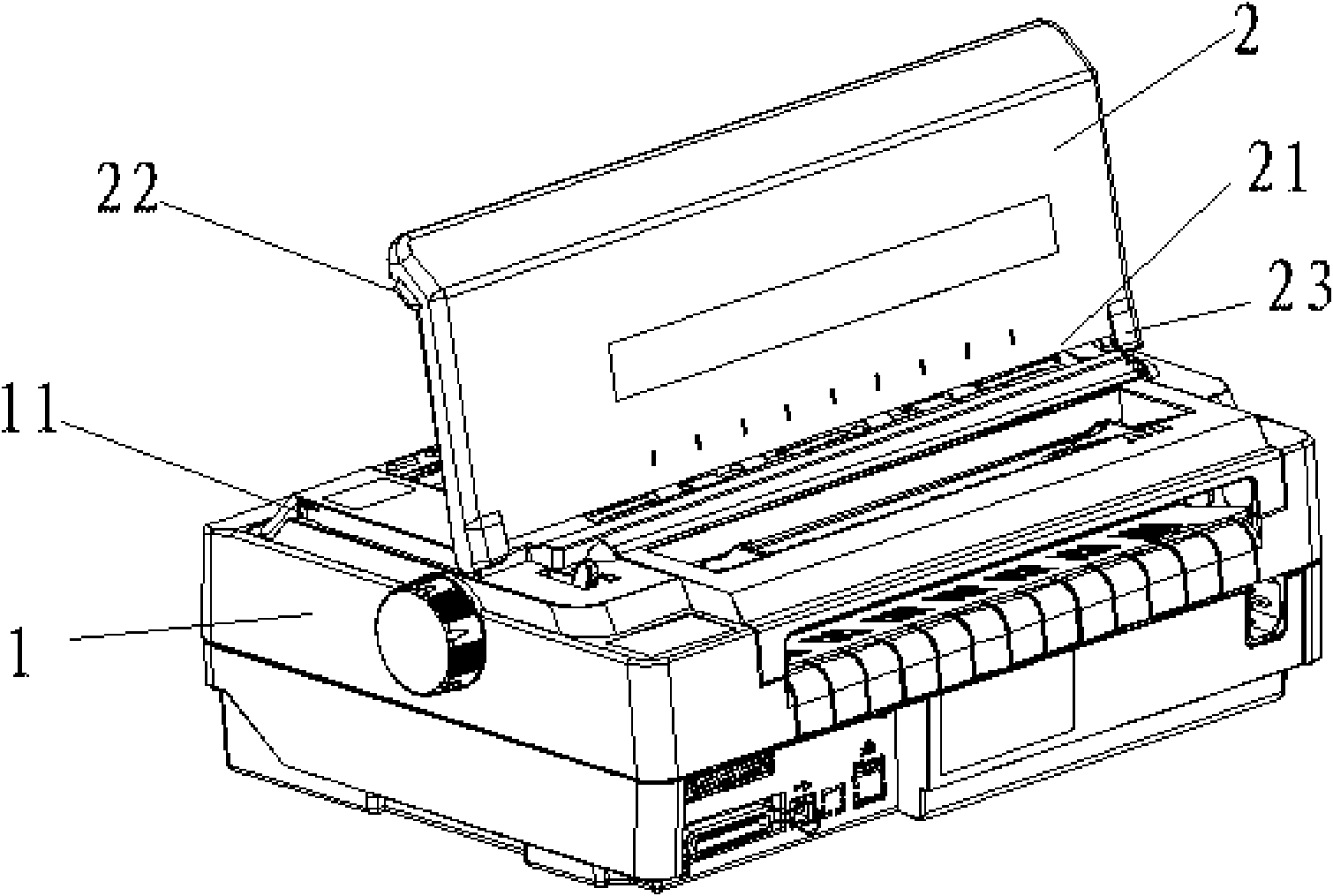
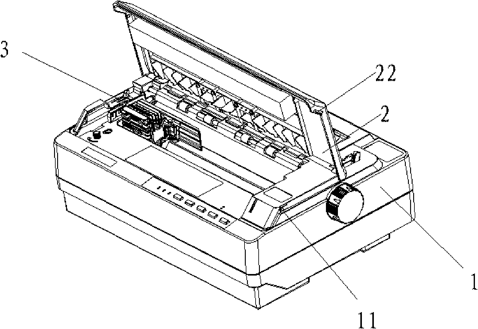
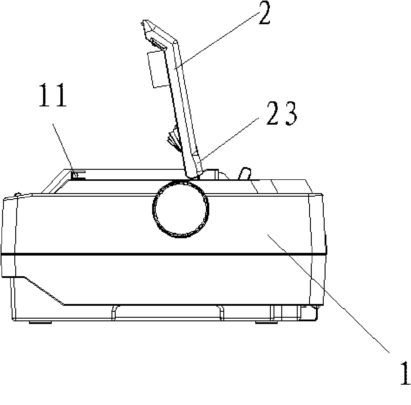
[0013] refer to figure 1 , 2 , 3, a rear hinged printer cover structure with paper tearing function, which includes a printer cover 2 hinged in the middle of the printer casing 1, the printer cover 2 is sealed and covered on the printing device 3, the printer A tearing edge 21 is provided on the side of the paper outlet of the upper cover 2 , and the described tearing edge 21 is a beveled edge arranged on the side of the paper outlet of the printer upper cover 2 . Of course, according to actual needs, the paper tearing blade 21 can also adopt other structural forms.

[0014] In order to ensure that the tearing paper is more effective and tidy, the printer casing 1 is provided with a push-type boss structure 11 that is clamped on the inner side of the front end of the printer upper cover 2. This design enables the printer upper cover 2 to be firmly fastened on the on the printer case 1. In addition, the two sides of the front end of the printer top cover 2 are provided with ...


PUM


Abstract

The invention discloses an upper cover structure of a post articulated printer with a paper tearing function. The structure comprises an upper cover of the printer articulated at the middle part of the shell of the printer; the upper cover of the printer is hermetically covered on the printer; and a paper outlet at the upper cover of the printer is provided with a paper tearing edge. The upper cover structure replaces a metal knife edge of the old product with the paper tearing edge formed on the front end of the upper cover of the printer to realize the paper tearing function, and matches with the design of a front articulation position, so that when tearing the paper, the front end of the upper cover of the printer can be fixedly fastened to more effectively and trimly tear the paper.

Description

technical field [0001] The invention relates to a printer top cover, in particular to a printer top cover structure with a paper tearing function. Background technique [0002] At present, the upper cover of traditional printers is usually covered on the print head, which mainly plays a dust-proof function, but some printers use the upper cover as a tearing blade at the same time, but because the upper cover is hinged on the front of the printer, so When continuous paper is torn, the upper cover is usually lifted, which leads to tearing difficulties, so developing a more efficient and tidy upper cover structure for tearing continuous paper has been put on people's research agenda. Contents of the invention [0003] In order to overcome the deficiencies of the prior art, the present invention provides a more efficient and neater upper cover structure for tearing continuous paper. [0004] The technical solution adopted by the present invention to solve its technical proble...

Claims


Application Information

Patent Timeline
Patent Type & Authority Applications(China)
IPC IPC(8): B41J29/13
Inventor 袁兆祯梁钊伟梁岐江
Owner KONG YUE ELECTRONICS & INFORMATION IND XIN HUI
Learn More