
Electronic device with luminous grain shell

A technology for electronic devices and housings, which is applied to lighting devices, lighting devices, components of lighting devices, etc., can solve the problem that the housing cannot be effectively displayed, and achieve the effect of changing appearance

Inactive Publication Date: 2010-03-10
PEGATRON
View PDF0 Cites 0 Cited by
  • Summary
  • Abstract
  • Description
  • Claims
  • Application Information

AI Technical Summary

Problems solved by technology

[0004] However, when the ambient light source is insufficient, the seemingly three-dimensional graphics on the casing of the electronic product cannot be effectively displayed

Method used


Image

  • Electronic device with luminous grain shell
  • Electronic device with luminous grain shell
  • Electronic device with luminous grain shell

Examples


Embodiment Construction

[0020] The following will clearly illustrate the spirit of the present invention with the accompanying drawings and detailed descriptions. After those skilled in the art understand the embodiments of the present invention, they can be changed and modified by the techniques taught in the present invention without departing from the present invention. spirit and scope.

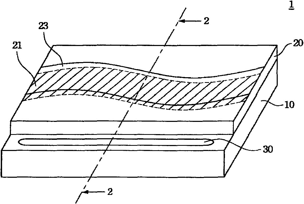
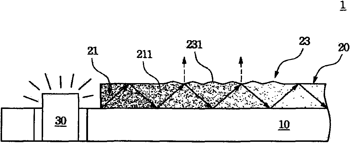
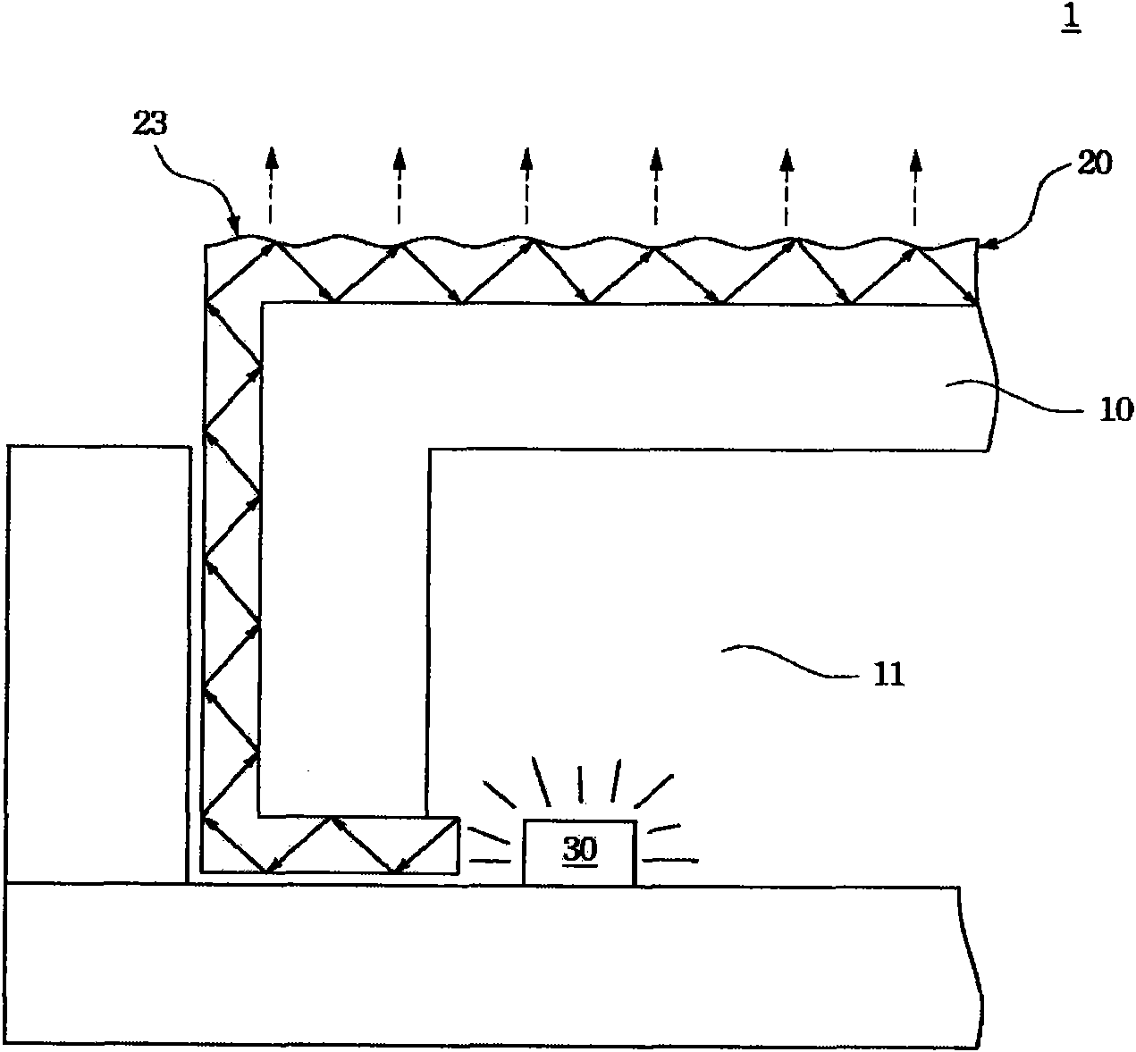
[0021] The present invention discloses a casing of an electronic device with luminous lines, please refer to figure 1 and figure 2 as shown, figure 1 It is a structural schematic diagram of the shell with luminous texture of the present invention, figure 2 for figure 1 The cross-sectional view and schematic diagram of light movement. The electronic device has a housing 1 and a light source 30. The housing 1 at least includes a housing 10 and a decorative laminate 20. The decorative laminate 20 is located on the housing 10 adjacent to the light source 30, and has a light guide layer 21 and A decorative lig...


PUM


Abstract

The invention relates to an electronic device with a luminous grain shell, which comprises a shell, a decorative lamination and a light source. The light source is arranged at the shell. The decorative lamination is positioned on the surface of the shell, and the lateral surface of the decorative lamination is adjacent to the light source. The decorative lamination is provided with a guide light grain layer and a decorative light grain layer, wherein the decorative light grain layer is arranged on the decorative lamination. When the light source does not emit the light, the decorative light grain layer reflects rays of an environmental light source to present a decorative light grain on the shell. When the light source emits the light, the guide light grain layer uses the rays of a guide light source to present a guide light grain at the position of the shell with the decorative light grain.

Description

technical field [0001] The invention relates to an electronic device, in particular to an electronic device with a light-emitting pattern shell. Background technique [0002] With the advancement of science and technology and the improvement of living standards, the appearance and decoration of electronic products (such as mobile phones or notebook computers) has become one of the considerations for consumers to choose electronic products. In this way, in addition to the performance and efficiency of electronic products, the quality of electronic products The industry pays more attention to the appearance and decoration of electronic products. In order to pursue more fashionable and changeable electronic products, the industry has successively developed an In-Mold Decoration (IMD) technology, including such as In-Mold Molding (In- Mold Forming (IMF), In-Mold Roller (IMR) and other technologies, in which the In-Mold Transfer technology (IMR) before the plastic is injected int...

Claims


Application Information

Patent Timeline
Patent Type & Authority Applications(China)
IPC IPC(8): F21V33/00F21V3/02F21V7/10F21W121/00F21Y101/02
Inventor 侯建旭
Owner PEGATRON
Learn More