
Optical disc drive

An optical disc device and optical disc technology, which are applied to optical recording/reproducing, ticketing equipment, instruments, etc., can solve problems such as insufficient strength, and achieve the effect of good convenience in use

Inactive Publication Date: 2010-03-03
HITACHI-LG DATA STORAGE
View PDF2 Cites 0 Cited by
  • Summary
  • Abstract
  • Description
  • Claims
  • Application Information

AI Technical Summary

Problems solved by technology

This is a necessary condition for easy carrying, but at the same time, the lack of strength becomes a problem when vibration and shock are applied from the outside

Method used


Image

  • Optical disc drive
  • Optical disc drive
  • Optical disc drive

Examples


Embodiment Construction

[0031] Below, while using the attached Figure 1 Embodiments of the present invention will be described.

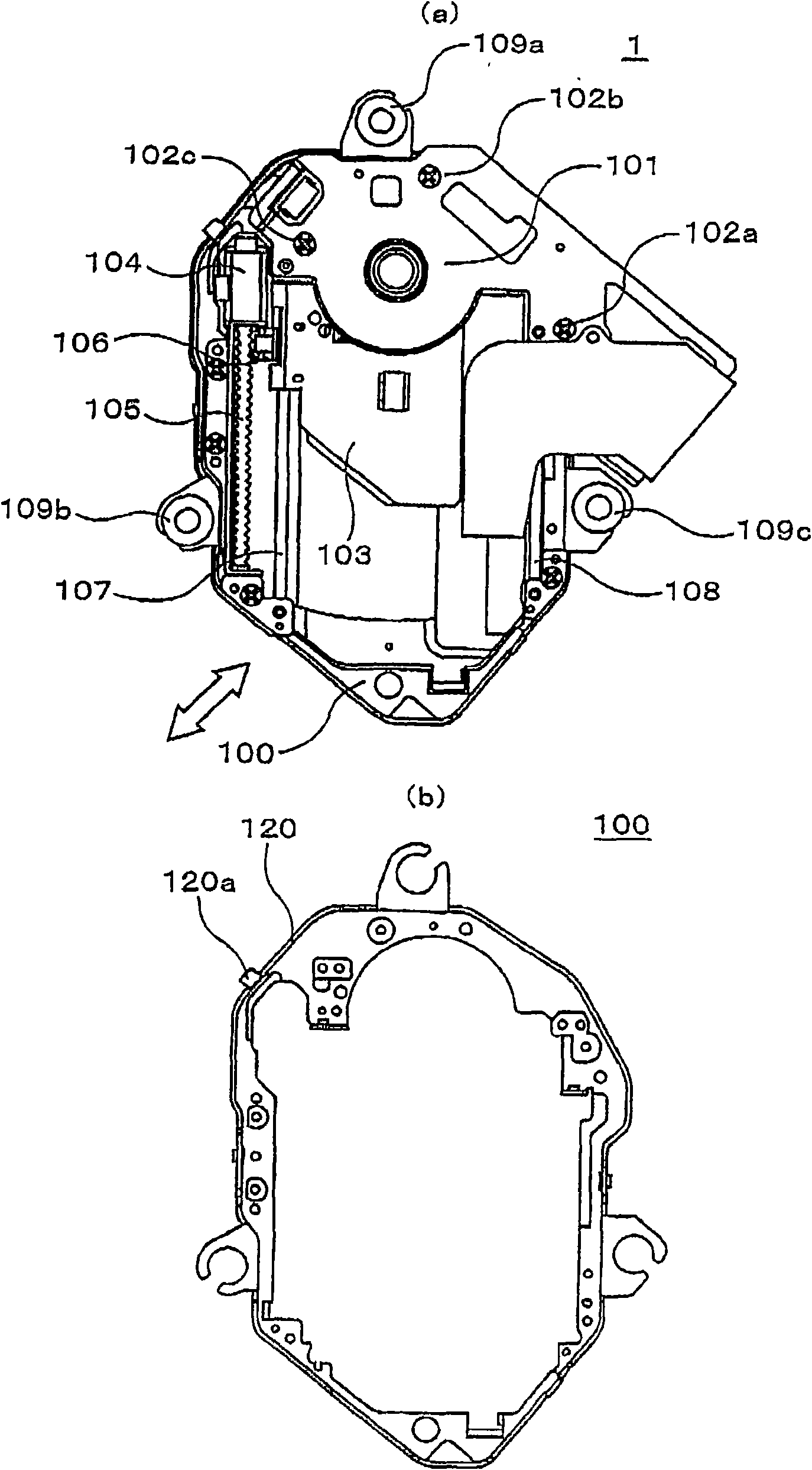
[0032] figure 1 A plan view showing an optical drive core mechanism assembly (hereinafter, abbreviated as TRV mechanism) 1 of the optical disk device of the present invention viewed from the bottom side of the device. The TRV mechanism houses the most important components of the mechanism system related to the recording and reproducing operation of the optical disc device, including a disc motor for rotating the optical disc, an optical pickup unit for recording and reproducing signals, and its moving mechanism. figure 1 (a) represents the whole of the TRV mechanism 1, figure 1 (b) shows the optical drive core 100 as a base portion therein. figure 1 The arrow at the lower left of (a) indicates the direction in which an unillustrated optical disc moves when it is loaded into or ejected from the optical disc device. When loading or ejecting a disc, the disc tray that lo...


PUM


Abstract

The invention provides an optical disc drive. Along with the reduction of the thickness and the weight of the optical disc drive, the resistance of optical disc drive to vibration and impact becomes aproblem. When a TRV mechanism moves long and deforms in particular, when an overturning moment is generated in the disc motor when the bottom face of the optical disc drive is subjected to an impact.The invention provides an optical disc drive that can secure resistance to vibration and impact without the addition of another part. A protrusion is formed by bending a part of a skirt at the periphery of a TRV mechanism, or a protrusion is formed at the periphery of a traverse cover, and the protrusion faces a disc tray forming a slight gap in between. When impact is imposed, the protrusion isbrought into contact with the disc tray and thereby the TRV mechanism is prevented from largely deforming without adding another part in order to enhance the resistance.

Description

technical field [0001] The present invention relates to an optical disc device, and particularly relates to an optical disc device capable of reducing deformation of mechanical parts caused by external vibrations and shocks. Background technique [0002] In portable PC (Personal Computer; Personal Computer), DVD (Digital Versatile Disc; Digital Versatile Disc) camcorder / recorder, BD (Blu-ray Disc; Blu-ray Disc) camcorder / recorder, etc. Thinning and lightweighting are progressing. This is a necessary condition for easy portability, but at the same time, insufficient strength becomes a problem when vibration and shock are applied from the outside. In particular, when the mechanical part is deformed, it greatly affects the drive performance such as the track trace performance on the optical disc. [0003] Patent Document 1 for solving this problem discloses that by providing a mounting piece having a spacer in a recording and reproducing unit, the thickness of the device can ...

Claims


Application Information

Patent Timeline
Patent Type & Authority Applications(China)
IPC IPC(8): G07B7/00
CPCG11B7/08582G11B17/056G11B33/121
Inventor 桐原聪二郎山岸浩
Owner HITACHI-LG DATA STORAGE
Learn More