System and method for adjusting brightness point by point

A brightness adjustment, point-by-point technology, applied in the direction of cathode ray tube indicators, lighting devices, light sources, etc., can solve the problems of different LED lamp panel parameters, difficult to accurately control and adjust the current, low work efficiency, etc. Uniform, widely accepted and efficient results

Active Publication Date: 2013-08-28
苏州卫优知识产权运营有限公司
View PDF1 Cites 0 Cited by
  • Summary
  • Abstract
  • Description
  • Claims
  • Application Information

AI Technical Summary

Problems solved by technology

In this way, each point needs to be valued one by one, the operation is cumbersome, the system is complicated, the time is too long, the manual operation is too much, the precision is low, and the work efficiency is low.
[0003] The Chinese application number is: 200710076632.6 invention, and its name is: a brightness data acquisition method and its equipment for LED brightness correction. The disadvantages of the modulation method and the current modulation method are: first, the change of the driving current and the brightness is not proportional, and it is difficult to accurately control and adjust the current with the change of the brightness; second, the parameters of different types of LED lamp panels are different, and the driving current and brightness The relationship curve is also different, and it needs to be recalculated each time; the third is that the change of the driving current will cause the change of the chromaticity, so changing the current to adjust the brightness will also cause the chromaticity to change. After this adjustment, when the brightness of the screen changes It will cause the difference in chromaticity and make the image chromaticity deviate

Method used


Image

  • System and method for adjusting brightness point by point
  • System and method for adjusting brightness point by point
  • System and method for adjusting brightness point by point

Examples


Embodiment 1

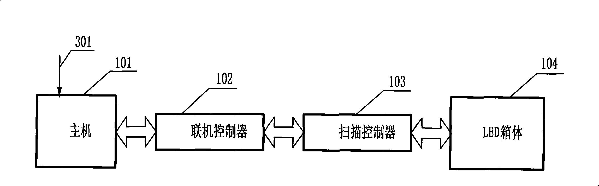
[0042] Refer to attached picture figure 1 and image 3 , its display system includes: a host computer 101 provided with an LED management tool module, used to transmit video signals and control signals to the online controller 102, and control the LED cabinet 104 through the LED management tool module; the online controller 102 uses After receiving the video signal and the control signal, process the video signal according to the control signal to obtain video data and send it to the scan controller 103; the scan controller 103 with a storage module is used to receive the Video data, according to the configuration file of the LED box 104 of the storage module, process the video data, generate display data, and send it to the LED box 104; the LED box 104 is connected to the scan controller 103, The display data is received and displayed.

[0043] The user inputs 301 the content to be displayed through an external input device, the host 101 processes the user input to form a D...

Embodiment 2

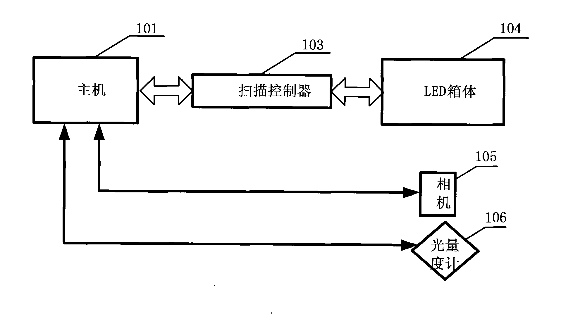
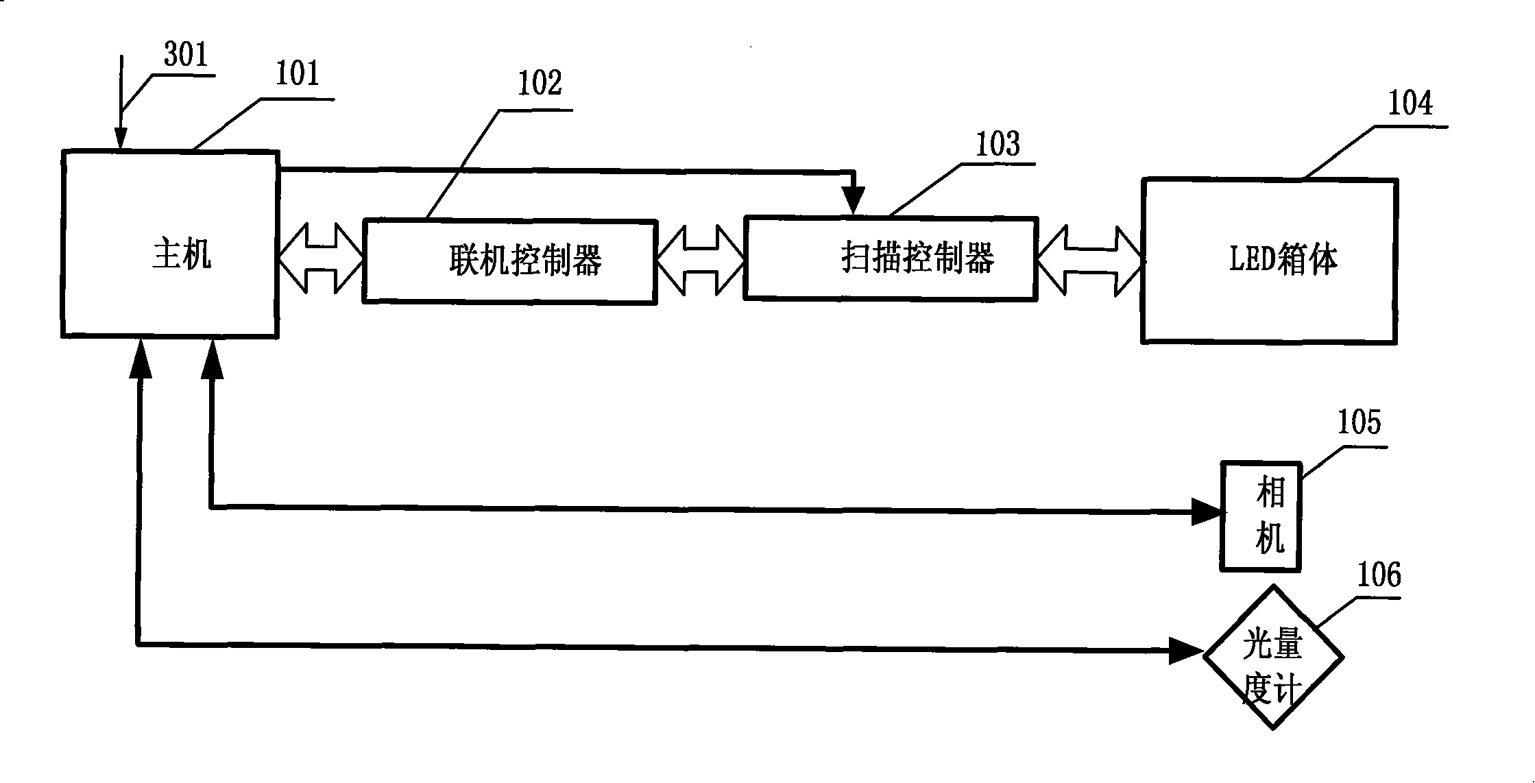
[0045] Refer to attached picture figure 2 and image 3 , wherein the adjustment system includes: the host 101, which is also used to transmit, receive and process the image data of the camera 105 and the brightness data of the light meter 106, and adjust the light point of the LED box 104 according to the image data and the brightness data Brightness and uniformity; the host 101 can be equipped with a processing module to complete the functions of data transmission, reception and processing, and can also be provided with a transmission module, a reception module and a processing module to complete the functions of transmission, reception and processing respectively.

[0046] The camera 105 is used to obtain the brightness of the LED box 104 lamp point, and sends the image data to the host 101; the light meter 106 is used to measure the overall brightness of the LED box 104, and sends the brightness data to the host computer 101. in the host 101.

[0047] The host 101 sends ...

Embodiment 3

[0050] Refer to attached picture Figure 4 and Figure 5 , Before the system runs, the environment should be established and the system built. Firstly, after placing the LED box 104 at the designated shooting position, light the LED box 104 .

[0051] Calculate and place the positions of the camera 105 and the light meter 106. The angle between the distance from the camera 105 to both sides of the LED box 104 and the vertical distance from the camera 105 to the LED box 104 is not more than 3 degrees. That is, the camera 105 is placed directly in front of the LED box body 104, and on the transverse central axis of the LED box body 104, the distance from the camera 105 to both sides of the LED box body 104 forms an isosceles triangle with the LED box body 104, with two waists The included angle is less than or equal to 6 degrees.

[0052] Calculation of the distance: R is the radius of the LED box, L is the vertical distance from the camera to the LED box, a is the angle betw...


PUM


Abstract

The invention relates to a system and a method for adjusting brightness point by point. The system comprises a host computer, an online controller, a scanning controller, an LED case, a camera and a light quantity measuring instrument. The method for the system for adjusting the brightness point by point to adjust the brightness and the uniformity comprises the following steps: A, lightening the LED case, performing calculation, and placing well the positions of the camera and the light quantity measuring instrument; B, controlling the camera by the host computer to take pictures of the LED case automatically, and adjusting the brightness uniformity of lamp points on the LED case; and C, controlling the light quantity measuring tool by the host computer to measure the overall brightness of the LED case automatically, and adjusting the brightness of the lamp points on the LED case. By using the system and the method, firstly, the one-time acquisition of the brightness of the lamp points on the LED case is achieved, and the data is accurate; and secondly, by adopting the system, the operation is simple and fully automatic, the effect of the LED lamp points is obvious after the adjustment and is presented immediately.

Description

technical field [0001] The invention belongs to the technical field of image display adjustment, and in particular relates to a system structure and a realization method for point-by-point brightness adjustment of LED display. Background technique [0002] The LED screen is composed of hundreds of thousands or even millions of semiconductor light-emitting diodes, namely: LED light points. Various factors such as different optical properties of the light points, component aging, drive error, inconsistency in the angle of the light point itself, dust on the light point, and shielding of the hat brim to protect the light point will cause uneven brightness of the light point on the screen. At present, the main ways to solve this uneven phenomenon: one is to improve the consistency of the optical characteristics of LED lights, and the other is to improve the uniformity of the display screen by means of correction. The consistent way to improve the optical characteristics of LED ...

Claims


Application Information

Patent Timeline
Patent Type & Authority Patents(China)
IPC IPC(8): G09G3/32G09G5/10H05B37/02
Inventor 管丽邵寅亮李伟
Owner 苏州卫优知识产权运营有限公司
Why Eureka
Try Eureka