Rotary control flashlight

A flashlight and control technology, applied in the field of flashlights, can solve problems such as no brightness adjustment, inability to operate flexibly with one hand, etc.

Inactive Publication Date: 2010-01-27
陈康伟
View PDF0 Cites 1 Cited by
  • Summary
  • Abstract
  • Description
  • Claims
  • Application Information

AI Technical Summary

Problems solved by technology

Most of the rotary cylinder type is equipped with a contact piece in the flashlight, and the rotating cylinder causes the contact piece to contact or separate to realize the function of turning on or off the torch without brightness adjustment; some of them adjust the brightness through potentiometers and multi-level switches. But cannot be manipulated flexibly with one hand

Method used


Image

  • Rotary control flashlight
  • Rotary control flashlight

Examples


Embodiment Construction

[0009] Describe below in conjunction with accompanying drawing embodiment:

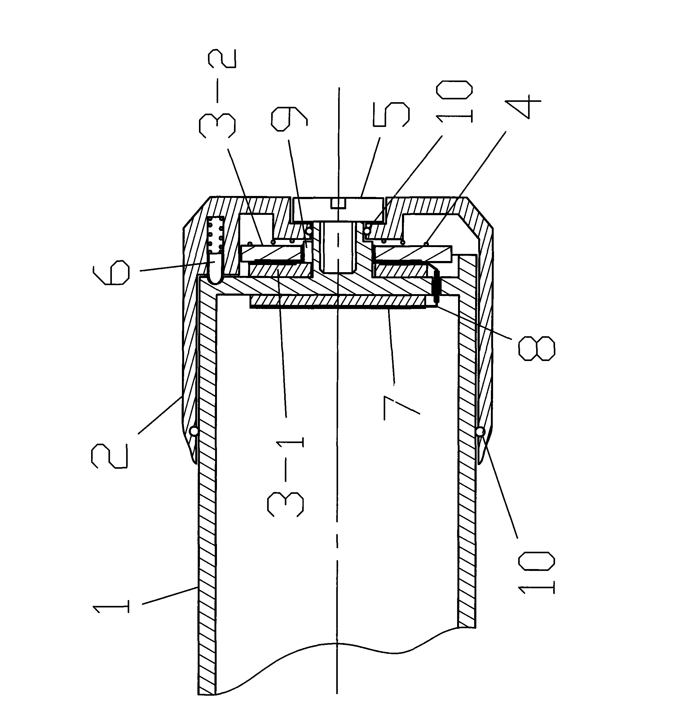
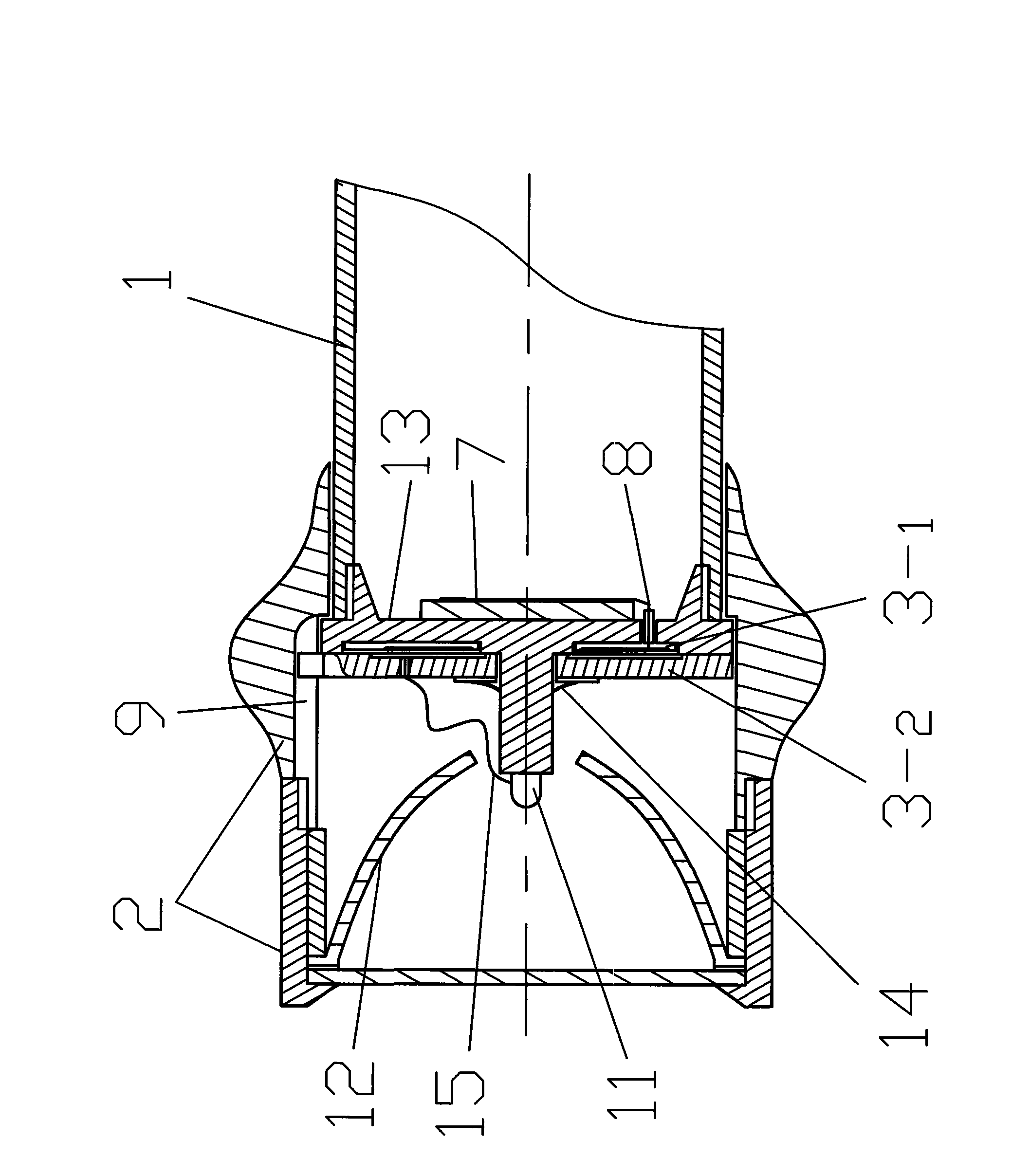
[0010] figure 1 In the shown embodiment, the rotatable part 2 is the tail of the torch, the body of the torch 1 is a conductor, the adjustable control part 3 is an adjustable resistor with an "off" position, and the fixed ring 3-1 of the adjustable control part 3 It is fixed on the flashlight body 1 by its own inner ring and card slot 9, the pins of the fixed ring 3-1 are electrically connected with the connecting plate 7 through the wire 8, and the pins of the moving ring 3-2 of the adjustable control part 3 The inner ring is electrically connected with the flashlight body 1, the sealing ring 10 is used for sealing and waterproofing, the spring 4 ensures that the fixed ring 3-1 is engaged with the moving ring 3-2, and the positioning top 6 is used for "off gear" positioning. When the rotatable part 2 is rotated relative to the torch body 1, the rotatable part 2 drives the moving ring 3-2 to rotate, ...


PUM


Abstract

The invention provides a rotary control flashlight. The rotary control flashlight has a rotatable body which can be flexibly rotated by a single hand by forehand or backhand holding of the flashlight, and can realize turning on, turning off, light adjustment, additional function (for example, SOS) selection.

Description

technical field [0001] The invention relates to a flashlight which can be turned on, off, adjusted brightness or added some functions (such as SOS) by rotating the head or tail of the flashlight. Background technique [0002] The switch forms of flashlights currently on the market include button type, toggle type, micro-touch type, and rotating cylinder type. Most of the rotary cylinder type is equipped with a contact piece in the flashlight, and the rotating cylinder causes the contact piece to contact or separate to realize the function of turning on or off the torch without brightness adjustment; some of them adjust the brightness through potentiometers and multi-level switches. But it cannot be manipulated flexibly with one hand. Contents of the invention [0003] The invention provides a rotary control flashlight which can be flexibly rotated with one hand to turn a rotatable part of the cylinder body while holding the flashlight in the forehand or the backhand, so a...

Claims


Application Information

Patent Timeline
IPC IPC(8): F21L4/00F21V14/00F21V23/04
Inventor 陈康伟
Owner 陈康伟
Why Eureka
Try Eureka