
Double-circle polarization and difference beam broadband corrugation horn feed antenna

A dual circularly polarized, corrugated horn technology, used in waveguide horns, antennas, electrical components, etc., can solve the problems of difficult alignment of feeding points, unsatisfactory circular polarization axis ratio, etc., and achieve a good circular polarization axis ratio. Effect

Active Publication Date: 2012-11-21
CHINA ELECTRONIC TECH GRP CORP NO 38 RES INST
View PDF5 Cites 0 Cited by
  • Summary
  • Abstract
  • Description
  • Claims
  • Application Information

AI Technical Summary

Problems solved by technology

[0003] In order to solve the problems that the existing dual circular polarization and differential beam feed antennas have unsatisfactory circular polarization axis ratio and difficult to arrange the feeding points in the half-wavelength space, the present invention provides a new structure of dual circular poles Sum and Difference Beam Broadband Corrugated Horn Feed Antenna

Method used


Image

  • Double-circle polarization and difference beam broadband corrugation horn feed antenna
  • Double-circle polarization and difference beam broadband corrugation horn feed antenna
  • Double-circle polarization and difference beam broadband corrugation horn feed antenna

Examples


Embodiment 1

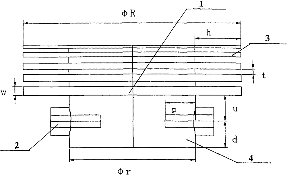
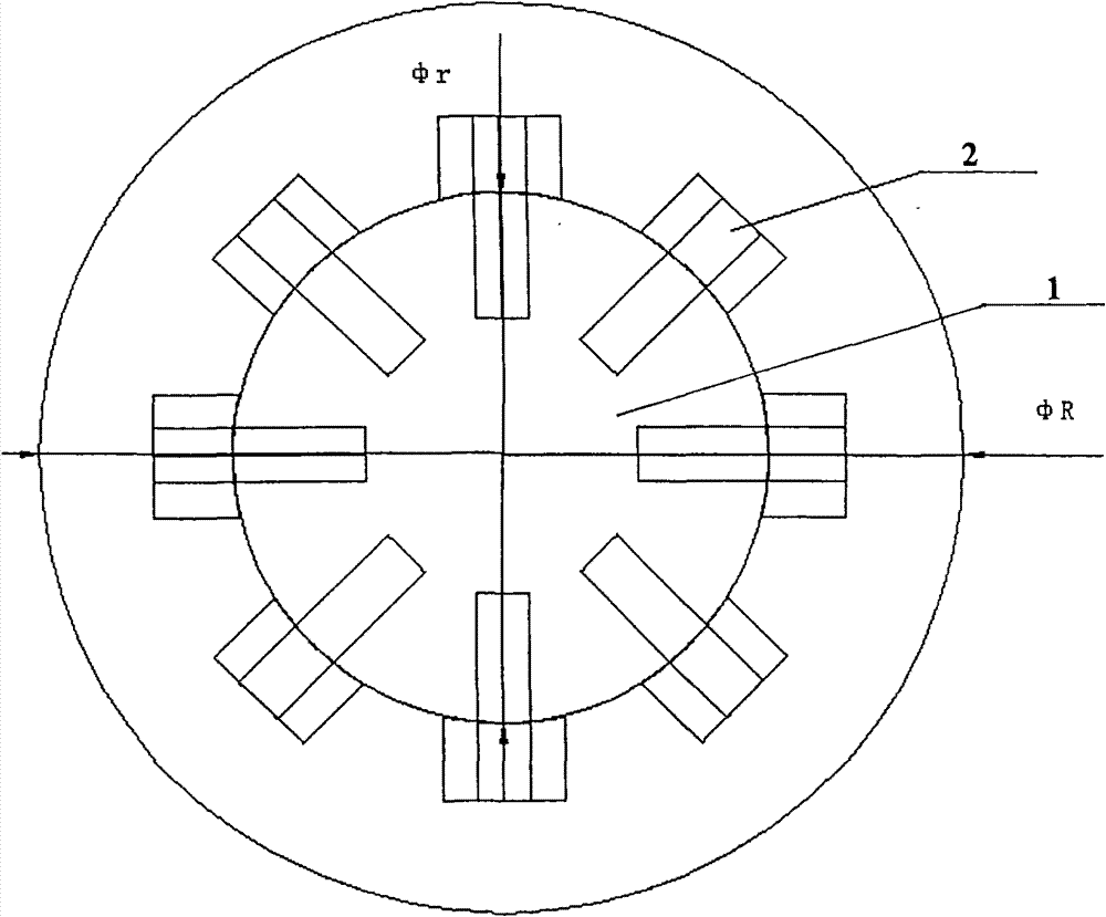
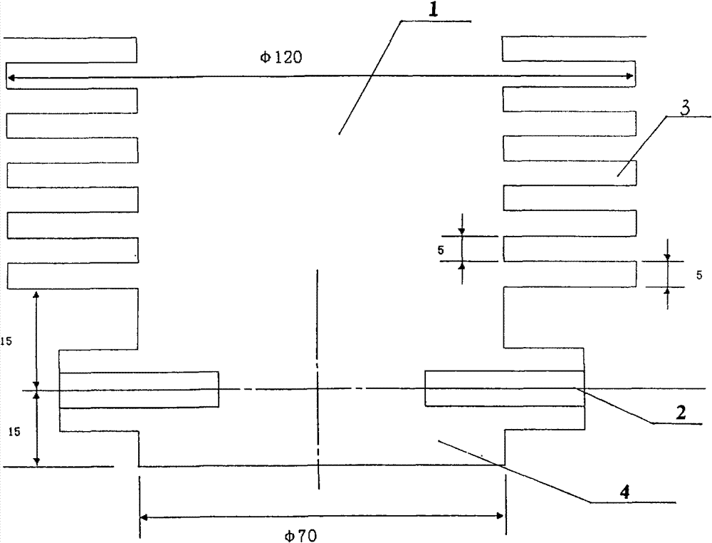
[0028] Now take the frequency 4.1GHz~6.9GHz feed antenna as an example to further illustrate the present invention, its center frequency is 5.5GHz, and its antenna size is shown in image 3 , see the measured lobe diagram Figure 4 ~ Figure 9 .

[0029] see figure 1 and figure 2 , the dual circular polarization and differential beam broadband corrugated horn feed antenna includes an antenna body 1 and a coaxial probe 2 . The antenna body 1 is cylindrical, the upper part is a corrugated part 3 , and the lower part is a feeding part 4 . The corrugated part of the upper part of the antenna body 1 is evenly distributed in the radial direction with five ring grooves, the groove depth of which is 1 / 4 wavelength of the center frequency, and the groove width and groove spacing are both less than 1 / 10 of the center frequency wavelength, respectively 5 mm ; And the slot width w and the slot spacing t are equidistant; the diameter of the corrugated part of the antenna body 1 is 120...

Embodiment 2

[0032] see figure 1 , the groove width w and the groove spacing t of the corrugated part of the present invention can also be gradually changed, which is determined according to the bandwidth requirement. Its feed part adopts six coaxial probes to feed power.


PUM


Abstract

The invention relates to a double-circle polarization and difference beam broadband corrugation horn feed antenna comprising an antenna body and a coaxial probe, wherein the antenna body is in a cylindrical shape, the upper part of the antenna body is provided with a corrugation part, the lower part of the antenna body is provided with a feed part, more than two ring grooves are evenly distributed in the radial direction of the corrugation part, the groove depth of the ring grooves is 1 / 4 wavelength of center frequency, a groove width and a groove space are smaller than 1 / 10 wavelength of thecenter frequency, more than six coaxial probes are evenly arranged on the radial direction of the feed part, the extended distance of the coaxial probes in the antenna body is 1 / 4 wavelength of the center frequency, and the distances from the axial center of the coaxial probes to the bottom of the ripple part and from the axial center of the coaxial probes to the bottom of the feed part are 1 / 4 wavelength of the center frequency. The double-circle polarization and difference beam broadband corrugation horn feed antenna adopts the coaxial probes to excite a circular waveguide side wall and realizes favorable circular polarization and difference beams, and the feed method can be used for a higher frequency band. The double-circle polarization and difference beam broadband corrugation horn feed antenna can be used for a high frequency-band broadband double-polarization single pulse feed resource and can achieve a favorable circular polarization axial ratio in a frequency band range of 60percent.

Description

technical field [0001] The invention relates to a wide-band dual-polarized single-pulse feed antenna that can be used in high-frequency bands. Background technique [0002] In the field of electronic countermeasures and telemetry, with the development of wide-band and multi-polarized target signals, higher requirements are put forward for self-tracking systems. Most of the traditional broadband self-tracking antennas are below the X-band, and the broadband dual-polarization self-tracking antennas with higher frequency bands are rarely reported at home and abroad. At present, the commonly used dual circular polarization and differential beam feed antennas are composed of multiple linearly polarized antennas to form a circular array, and sequential feeding is performed to achieve circular polarization. The linearly polarized antennas used in the array mostly use logarithmic period or Vivaldi Antennas, this way of forming an array brings two problems: one is that the ratio of ...

Claims


Application Information

Patent Timeline
Patent Type & Authority Patents(China)
IPC IPC(8): H01Q13/02H01Q13/08
Inventor 万笑梅李刚
Owner CHINA ELECTRONIC TECH GRP CORP NO 38 RES INST
Learn More