
Imaging apparatus

A camera device and image technology, applied in image communication, TV, color TV parts, etc., can solve the problem of not being able to intuitively identify the user's camera area, and achieve the effect of simple operation

Inactive Publication Date: 2009-12-09
SANYO ELECTRIC CO LTD
View PDF1 Cites 4 Cited by
  • Summary
  • Abstract
  • Description
  • Claims
  • Application Information

AI Technical Summary

Problems solved by technology

[0008] That is to say, in prior art 1, the user refers to the through-image displayed on the monitor during the imaging standby, and even when performing still image imaging or moving image imaging, the guide for still images is always displayed. The state of the frame and the guide frame for moving images cannot intuitively identify the imaging area that the user wants to capture, and may not be able to see the easy-to-see through image

Method used


Image

  • Imaging apparatus
  • Imaging apparatus
  • Imaging apparatus

Examples


Embodiment Construction

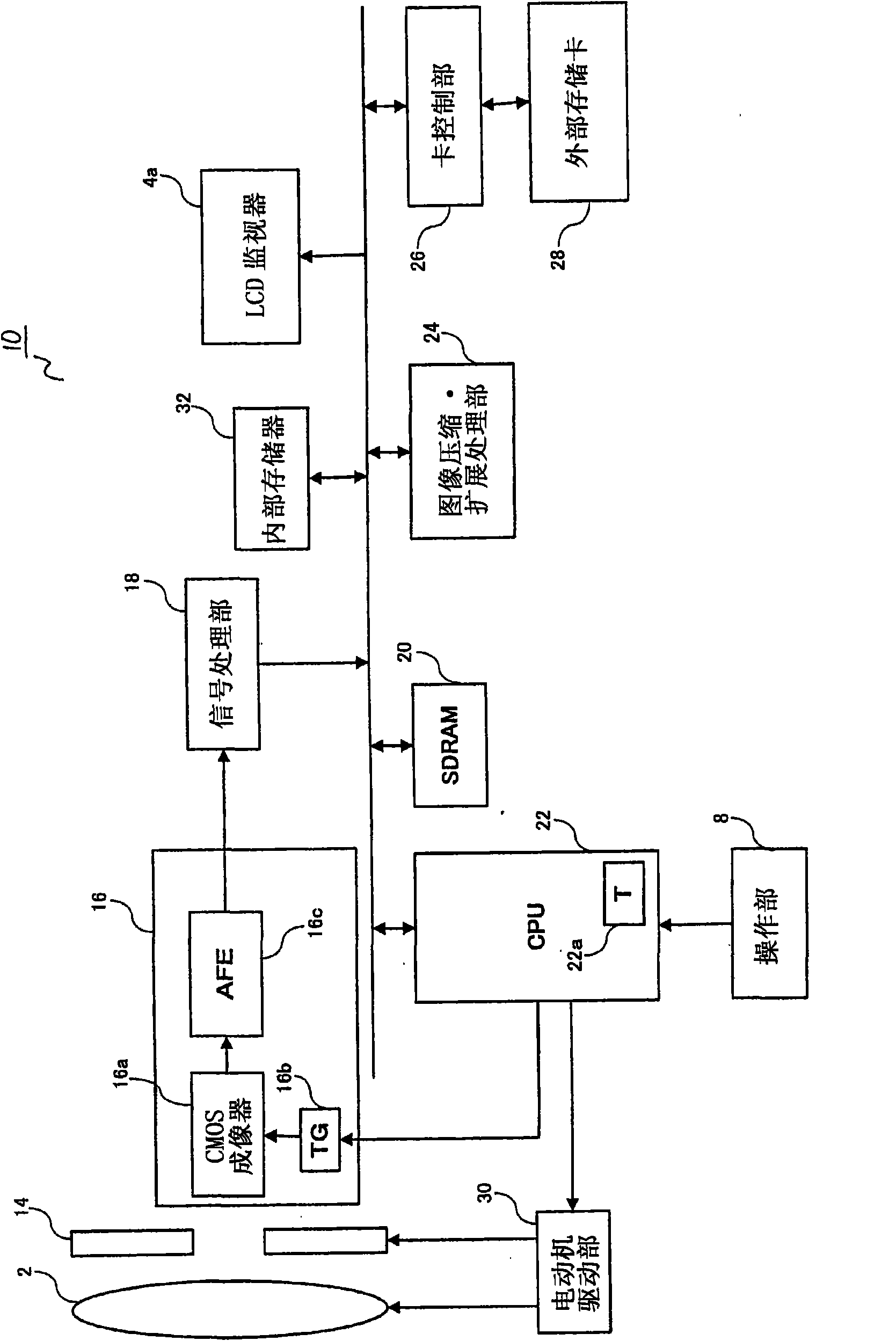
[0025] In this embodiment, the form of the electronic camera 10 will be described as an example of an imaging device.

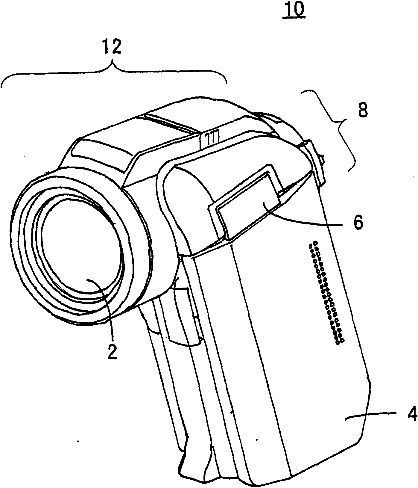
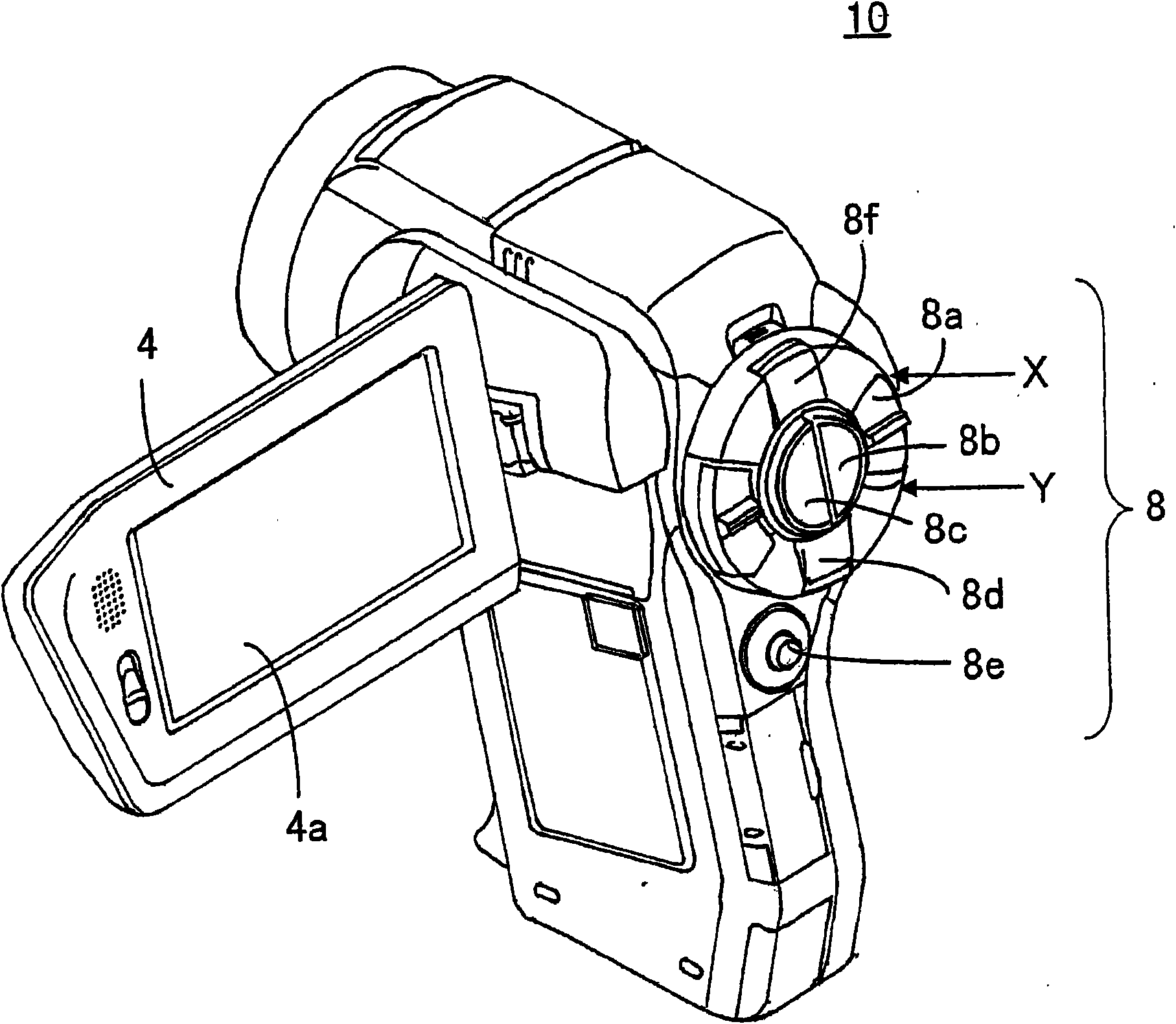
[0026] The appearance diagram of the electronic camera 10 is as follows: figure 1 and figure 2 shown. figure 1 It is a perspective view showing the front of the electronic camera 10, figure 2 It is a perspective view showing the back of the electronic camera 10 .

[0027] Such as figure 1 and figure 2 As shown, the electronic camera 10 includes an imaging unit 12 including at least a lens unit 2, a viewfinder unit 4 including an LCD monitor 4a, a hinge unit 6, and operation buttons 8a to 8f.

[0028] figure 1 It is a figure which shows the state which accommodated the viewfinder part 4 in the main body device which has the imaging part 12 so that the LCD monitor 4a may not be exposed. Usually, the user does not perform an imaging operation in such a form. figure 2 express figure 1 The back side of , shows a state where the viewfinder unit 4 is ro...


PUM


Abstract

An imaging apparatus fetches an optical image of an object so as to produce an image signal, records on a recording medium an image signal corresponding to a still-image-use image size according to a still-image recording instruction, records on the recording medium an image signal corresponding to a moving-image-use image size according to a moving-image recording instruction, repeatedly creates the image signal and causes a displayer to display a still-image-use through image corresponding to the still-image-use image size, repeatedly creates the image signal and causes the displayer to display a moving-image-use through image corresponding to the moving-image-use image size, switches the still-image-use through image and the moving-image-use through image, and accepts the still-image recording instruction or the moving-image recording instruction when the still-image-use through image or the moving-image-use through image is displayed.

Description

technical field [0001] The present invention relates to an imaging device, especially an imaging device capable of displaying a through image on a display if it has a recording function for recording still images and moving images, and performs displaying on the display of still images and moving images set by the user. Control of the through image of the imaging area corresponding to the image size. Background technique [0002] In recent years, video cameras capable of capturing and recording not only still images but also moving images over a long period of time have been commercialized. The captured moving image can be reproduced and displayed not only on a monitor equipped with the camera, but also on a television receiver such as a fixed pixel system such as a liquid crystal display or a CRT picture tube system connected to the camera. In addition, in recent years, television receivers capable of displaying high-definition images (HD: High Definition) are becoming pop...

Claims


Application Information

Patent Timeline
Patent Type & Authority Applications(China)
IPC IPC(8): H04N5/232
CPCH04N5/23245H04N5/23293H04N5/3454H04N5/2252H04N5/343H04N23/531H04N23/51H04N23/667H04N23/635H04N25/42H04N25/443
Inventor 市居伸彦坂地亮堺有里江
Owner SANYO ELECTRIC CO LTD
Learn More