Mapping method of reference signal and physical resource block
A technology of physical resource blocks and reference signals, applied in communication between multiple stations, multi-frequency code system, etc., can solve the problems of high complexity in the implementation of mapping methods
- Summary
- Abstract
- Description
- Claims
- Application Information
AI Technical Summary
Problems solved by technology
Method used
Image
Examples
Embodiment 7
[0060] Optional embodiment 7, there are 8 channels of multiple reference signals, mapping the 8 channels of reference signals to 4 OFDM symbols of the physical resource block, and mapping each channel of reference signals to M subcarriers on the OFDM symbols specifically includes the following At least one method:
[0061] Method 1: Map multiple reference signals in the first reference signal to the following time-frequency positions: subcarrier A, subcarrier A+4, and subcarrier (A+8) of the first OFDM symbol of the 4 OFDM symbols mod 12; multiple reference signals in the second reference signal are mapped to the following time-frequency positions: subcarrier A, subcarrier A+4, subcarrier (A+8) of the second OFDM symbol of 4 OFDM symbols mod 12; multiple reference signals in the third reference signal are mapped to the following time-frequency positions: subcarrier A+B, subcarrier A+4+B, subcarrier ( A+8+B) mod12; multiple reference signals in the fourth reference signal are ...
Embodiment 8
[0065] Optional embodiment 8, the multi-channel reference signal is 8 channels, mapping the 8-channel reference signal to 2 OFDM symbols of the physical resource block, and mapping each channel of reference signal to M subcarriers on the OFDM symbol specifically includes: Multiple reference signals in the first path of reference signals are mapped to subcarrier A, subcarrier A+4, subcarrier (A+8) mod 12 of the first OFDM symbol of two OFDM symbols; the second path of reference Multiple reference signals in the signal are mapped to subcarrier A+2, subcarrier A+6, and subcarrier (A+10) mod 12 of the second OFDM symbol of the two OFDM symbols; Multiple reference signals are mapped to subcarrier A+1, subcarrier A+5, and subcarrier (A+9) mod12 of the first OFDM symbol of two OFDM symbols; the multiple reference signals in the fourth path reference signal Map the second OFDM symbol of the two OFDM symbols to subcarrier A+3, subcarrier A+7, subcarrier (A+11) mod 12; map multiple refe...
example 1
[0082] This example describes the mapping of physical resource blocks for transmitting layer-1 reference signals in a subframe.
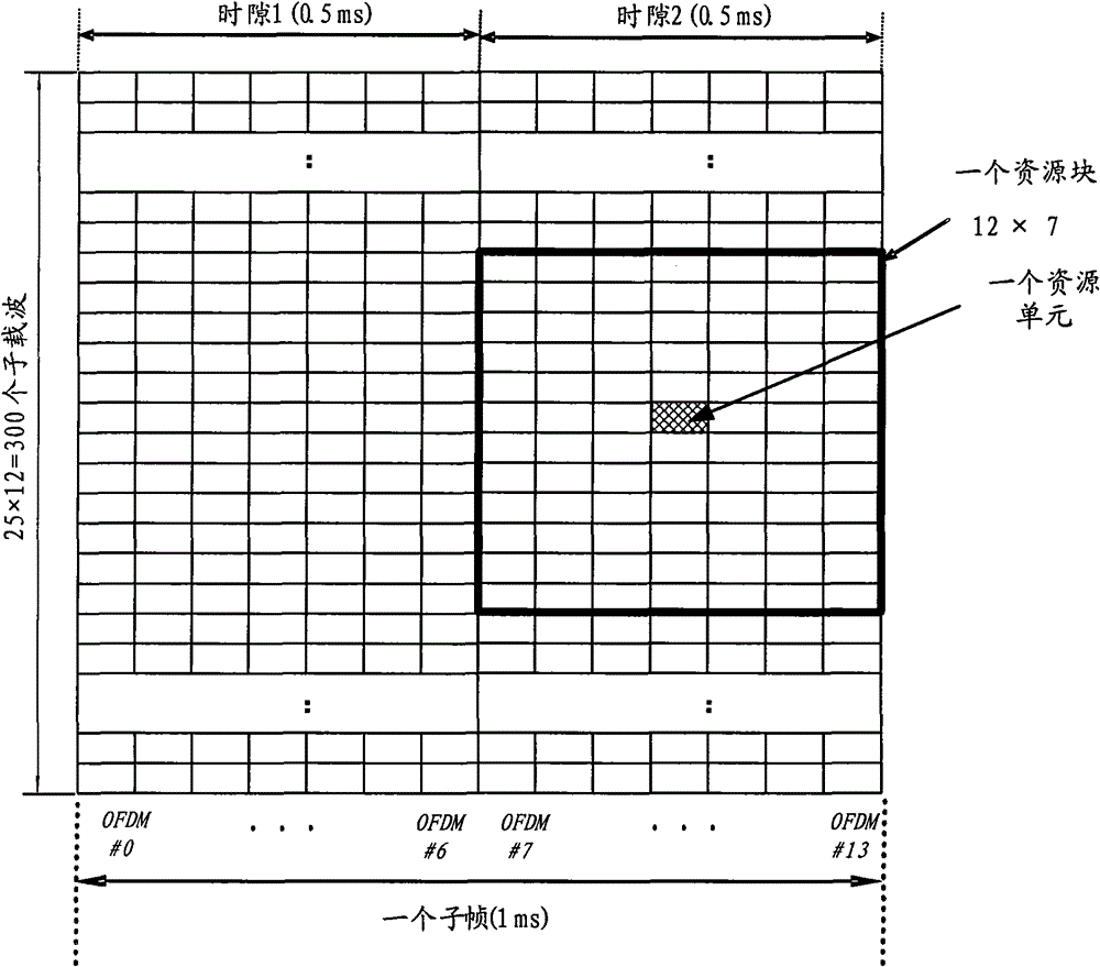
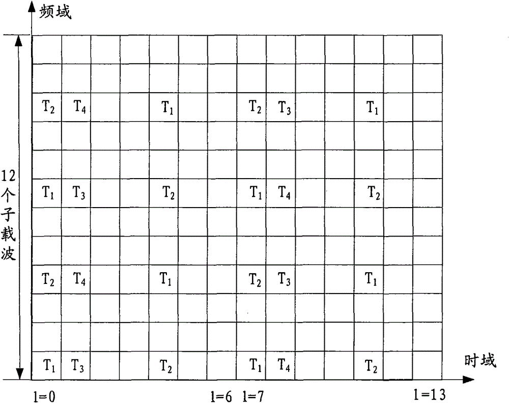
[0083] Figure 5a is a schematic diagram of the position of the reference signal in the physical resource block when the subframe adopts a conventional cyclic prefix, as shown in Figure 5a As shown, the reference signal #0 of layer 1 is included, and the physical resource block includes 12 subcarriers in the frequency domain and 14 OFDM symbols in the time domain, and A=0.
[0084] Map the reference signal #0 of layer 1 to the following time-frequency positions of the above physical resource block: subcarrier #0, subcarrier #4, subcarrier #8 of the fourth OFDM symbol, subcarrier # of the seventh OFDM symbol 2. Subcarrier #6, subcarrier #10, subcarrier #0, subcarrier #4, subcarrier #8 of the 10th OFDM symbol, subcarrier #2, subcarrier #6, subcarrier of the 13th OFDM symbol Carrier #10.
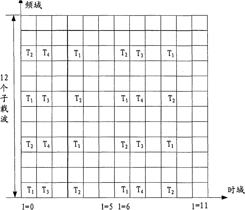
[0085] Figure 5b is a schematic diagram of the position o...
PUM
 Abstract
Description
Claims
Application Information
 - R&D
- Intellectual Property
- Life Sciences
- Materials
- Tech Scout
- Unparalleled Data Quality
- Higher Quality Content
- 60% Fewer Hallucinations
Browse by: Latest US Patents, China's latest patents, Technical Efficacy Thesaurus, Application Domain, Technology Topic, Popular Technical Reports.
© 2025 PatSnap. All rights reserved.Legal|Privacy policy|Modern Slavery Act Transparency Statement|Sitemap|About US| Contact US: help@patsnap.com


