Flow-volume regulator

A technology of flow regulator and jet flow regulator, which is applied in the direction of flow control without auxiliary power, indoor sanitary piping device, water supply device, etc.

Active Publication Date: 2009-11-18
NEOPERL
View PDF0 Cites 7 Cited by
  • Summary
  • Abstract
  • Description
  • Claims
  • Application Information

AI Technical Summary

Problems solved by technology

[0003] Although the fluid quantity can be adjusted to a predetermined maximum value at high pressures of the inflow fluid, the control gap...

Method used


Image

  • Flow-volume regulator
  • Flow-volume regulator
  • Flow-volume regulator

Examples


Embodiment Construction

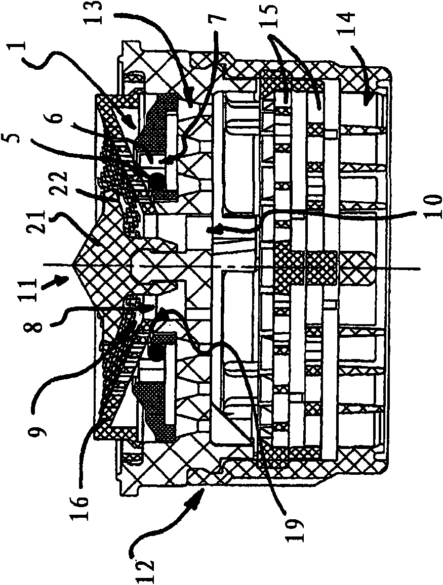
[0030] Figures 1 to 8 Different embodiments 1, 2, 3 and 4 of a flow regulator are shown in FIG. The flow regulators 1 , 2 , 3 and 4 are designed here as insert sleeves or components of an insert sleeve, which can be inserted into the discharge spout of a sanitary water valve (not shown again). It is also possible to interpose comparable flow regulators in a gas or liquid line.

[0031] The flow regulators 1 , 2 , 3 and 4 serve for this purpose to regulate the flow-through fluid quantity per unit time to a defined maximum value even at increasing inflow fluid pressures. The flow regulators 1 , 2 , 3 and 4 have for this purpose an annular throttle body 5 made of elastic material, which delimits between it and a housing wall 6 a pressure-changing pressure of the fluid flowing through. Control gap7. An adjusting profile consisting of a profile and a recess is provided on the housing wall 6 which Figure 7 and 8 It is constituted as an adjustment body embedded around the thro...


PUM


Abstract

The invention relates to a flow-volume regulator (1) having an elastic throttle body (5) which delimits, between itself (5) and a housing wall (6), a control gap (7) which changes under the pressure of the fluid flowing through. A characteristic of the inventive flow-volume regulator (1) is that the flow-volume regulator (1) has at least one associated bypass and/or cleaning channel (8) whose at least one channel inlet (9) is arranged before the control gap (7) in the direction of flow and whose at least one channel outlet (10) is arranged after the control gap (7) in the direction of flow, and that the bypass and/or cleaning channel (8) contains a valve (11) which can move, under the pressure of the oncoming fluid, from an open position against a restoring force into a closed position and which seals the bypass and/or cleaning channel (8) in its closed position. Since the inventive flow-volume regulator (1) lets an additional volume of the fluid through the bypass channel (8) when the oncoming fluid is at low pressure, the flow curve for the inventive flow-volume regulator (1) is significantly increased in the low pressure range, which results in an enormous increase in convenience for low-pressure applications.

Description

technical field [0001] The invention relates to a flow regulator comprising an elastic throttle body which defines between itself and a housing wall a control gap which changes under the pressure of a fluid flowing through it. Background technique [0002] Flow regulators of the type mentioned at the outset are known in various embodiments. The above-mentioned known flow regulators usually have an annular throttle body made of elastic material, which defines between itself and a housing wall a control gap that changes under the pressure of the fluid flowing through. With the increasing pressure of the fluid flowing through, the throttle body is pressed more and more into the adjusting profile, which is arranged on the adjusting core formed as the center or on the housing wall formed as the outer peripheral wall. Since the control gap narrows with increasing fluid pressure, a flow regulator of this type is able to regulate the quantity of fluid flowing through per unit time ...

Claims


Application Information

Patent Timeline
IPC IPC(8): G05D7/01
CPCE03C1/08
Inventor U·措勒尔
Owner NEOPERL
Why Eureka
Try Eureka