
drying box

A drying box and drying technology, applied in the field of drying box, can solve the problem of reducing the efficiency of motor/fan combination

Inactive Publication Date: 2011-11-30
ANDRITZ TECH & ASSET MANAGEMENT
View PDF0 Cites 0 Cited by
  • Summary
  • Abstract
  • Description
  • Claims
  • Application Information

AI Technical Summary

Problems solved by technology

This, of course, reduces the efficiency of the motor / fan combination

Method used


Image

  • drying box
  • drying box
  • drying box

Examples


Embodiment Construction

[0023] figure 1 is a partial schematic diagram of the drying box 1. The drying box is used to dry the fiber pulp web. The drying cabinet comprises a plurality of blowers 3, 5 for generating a positive pressure, ie a pressure in its interior 7 higher than the normal atmospheric pressure.

[0024] Typically, a drying box includes hundreds of blowers, and for the convenience of description figure 1 Only two are shown. Since drying boxes are well known, no comprehensive description of them has been given.

[0025] Each blower 3, 5 is driven by a motor 9, 11, which is connected via a shaft 13, 15 respectively. Optionally, the motor can be detachably connected to the blower through the shaft coupling 17 on the shaft 13 or other connection means. This allows the motor to be replaced without disassembling the blower. However, the reverse blocking device that will be described in figure 1 The motor shown in the lower part is still functional when it is fixedly connected to the b...


PUM


Abstract

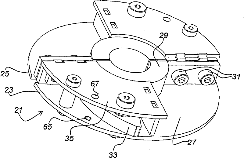
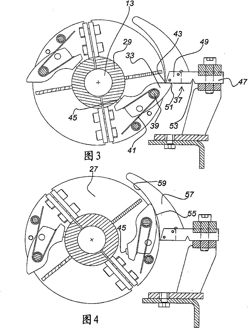
The invention relates to a drying box for drying a cellulose pulp web. The drying cabinet comprises a plurality of blowers (3, 5), each driven by a motor (9, 11) for generating a positive pressure inside the drying cabinet (7). The shaft between the motor (9) and the blower (3) is provided with a reverse blocking device (19), which prevents the blower from being reversely driven by the positive pressure in the drying box when the motor of the drying box is not working .

Description

technical field [0001] The invention relates to a drying box for drying a cellulose pulp web, said drying box comprising a plurality of blowers for generating a positive pressure inside the drying box, each blower driven by a motor in a first direction of rotation . The invention further relates to a cooling plate and a safety pin suitable for such a drying cabinet. Background technique [0002] Ovens of the type originally mentioned have been known for decades. Such ovens typically include hundreds of blowers to create a positive pressure inside them. Traditionally, rotary airflow operated regulators are located downstream of each blower. For example, in the event of a motor / fan combination failing, the regulator closes and maintains a certain level of pressure inside the oven. In addition, the regulator prevents the blower from being back driven by the pressure inside the drying cabinet, thus allowing maintenance of the motor / fan combination. [0003] One problem asso...

Claims


Application Information

Patent Timeline
Patent Type & Authority Patents(China)
IPC IPC(8): D21C9/18D21F5/18
CPCD21C9/18D21F5/18
Inventor T·维德罗斯A·诺伦高
Owner ANDRITZ TECH & ASSET MANAGEMENT
Learn More