Electronic blood pressure meter
An electronic sphygmomanometer, power supply voltage technology, applied in vascular assessment, cardiac catheterization, etc.
- Summary
- Abstract
- Description
- Claims
- Application Information
AI Technical Summary
Problems solved by technology
Method used
Image
Examples
Embodiment approach 1
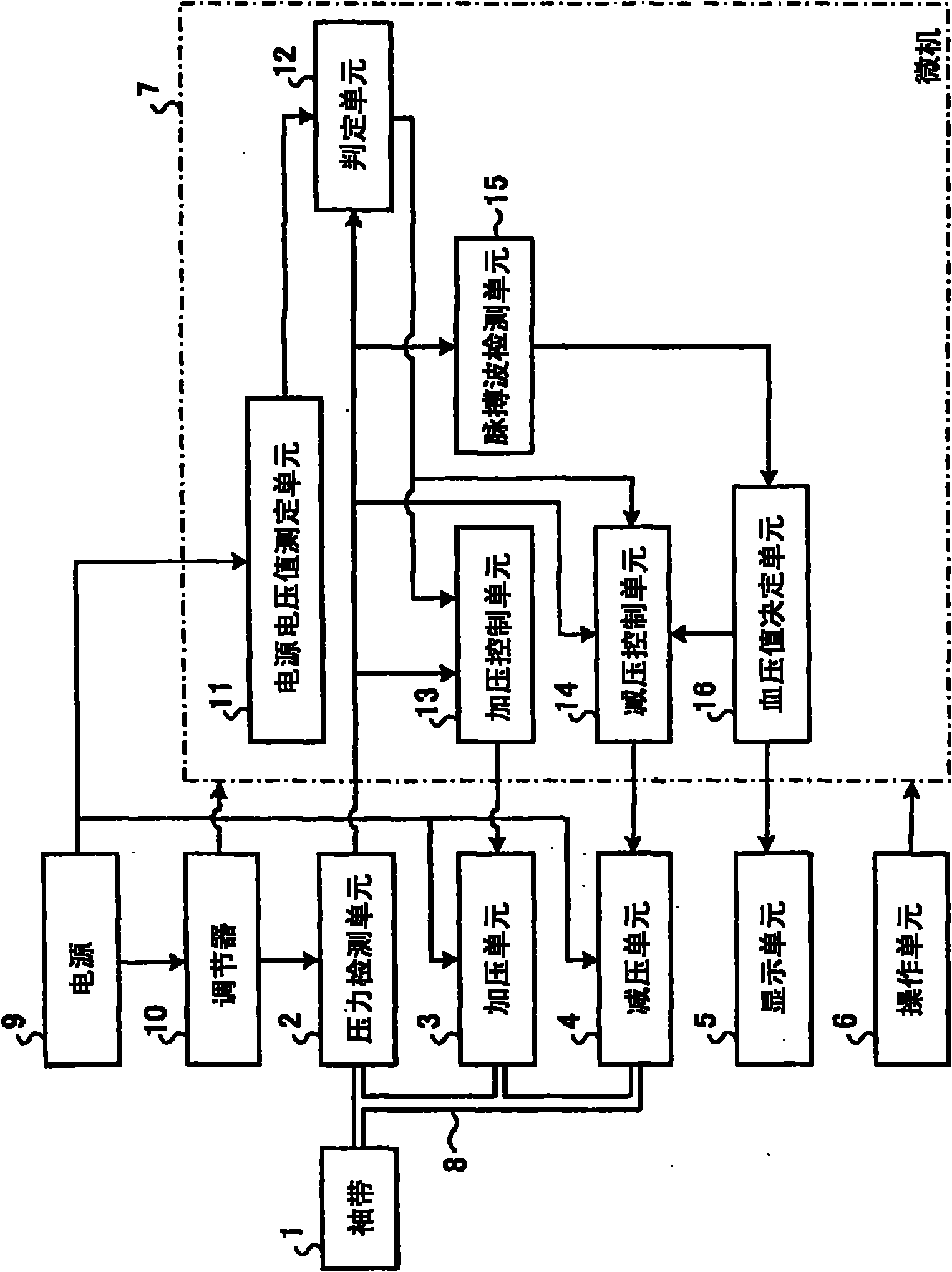
[0033] figure 1 It is a block diagram showing the overall configuration of the electronic sphygmomanometer according to Embodiment 1 of the present invention. like figure 1 As shown, the electronic sphygmomanometer has a cuff 1 , a pressure detection unit 2 , a pressurization unit 3 , a decompression unit 4 , a display unit 5 , an operation unit 6 , and a microcomputer (hereinafter referred to as a microcomputer) 7 . The cuff 1 , the pressure detection unit 2 , the pressurization unit 3 , and the decompression unit 4 are connected by a hose 8 .
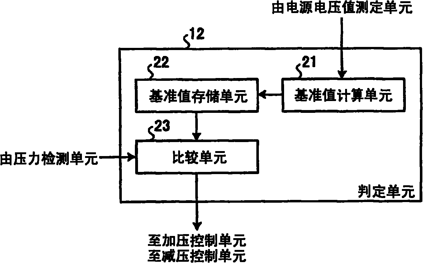
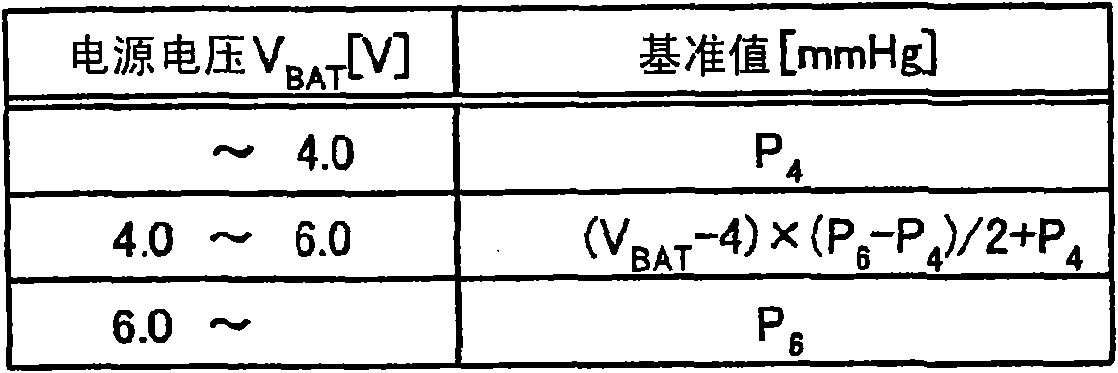
[0034] Driving voltages for the pressurization unit 3 and the decompression unit 4 are supplied from a power supply 9 . The power source 9 is constituted by a battery. Here, assume, for example, a case where four dry batteries having a nominal voltage (nominal voltage) of 1.5 volts are connected in series. Furthermore, the electronic sphygmomanometer incorporates a regulator 10 for stepping down the power supply voltage of the p...
Embodiment approach 2
[0063] The electronic sphygmomanometer of Embodiment 1 is an electronic sphygmomanometer that measures blood pressure while the cuff 1 is being decompressed at a slight speed, but the electronic sphygmomanometer of Embodiment 2 is an electronic sphygmomanometer that measures blood pressure while the cuff 1 is being pressurized. Therefore, the configuration of the electronic sphygmomanometer of Embodiment 2 differs from the configuration of the electronic sphygmomanometer of Embodiment 1 in the following points. In addition, the same reference numerals are assigned to the same configurations as in Embodiment 1, and overlapping descriptions are omitted.
[0064] Figure 8 It is a block diagram showing the overall configuration of the electronic sphygmomanometer according to Embodiment 2 of the present invention. like Figure 8 As shown, in the electronic sphygmomanometer of the second embodiment, the rapid exhaust unit 41 is provided as a decompression unit instead of the deco...
PUM
 Abstract
Description
Claims
Application Information
 - R&D Engineer
- R&D Manager
- IP Professional
- Industry Leading Data Capabilities
- Powerful AI technology
- Patent DNA Extraction
Browse by: Latest US Patents, China's latest patents, Technical Efficacy Thesaurus, Application Domain, Technology Topic, Popular Technical Reports.
© 2024 PatSnap. All rights reserved.Legal|Privacy policy|Modern Slavery Act Transparency Statement|Sitemap|About US| Contact US: help@patsnap.com


