Electronic blood pressure meter
An electronic sphygmomanometer, power supply voltage technology, applied in the direction of blood vessel evaluation, cardiac catheterization, etc., can solve the problem of misjudgment of cuff installation state and other problems, and achieve the effect of correct installation state
- Summary
- Abstract
- Description
- Claims
- Application Information
AI Technical Summary
Problems solved by technology
Method used
Image
Examples
Embodiment approach 1
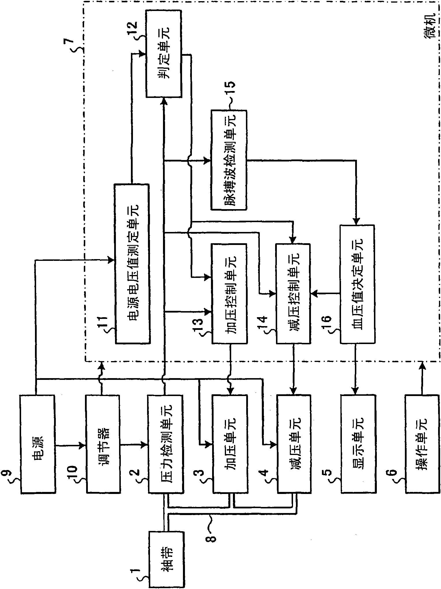
[0031] figure 1 It is a block diagram showing the overall configuration of the electronic sphygmomanometer according to Embodiment 1 of the present invention. Such as figure 1 As shown, the electronic sphygmomanometer has a cuff 1 , a pressure detection unit 2 , a pressurization unit 3 , a decompression unit 4 , a display unit 5 , an operation unit 6 , and a microcomputer (hereinafter referred to as a microcomputer) 7 . The cuff 1 , the pressure detection unit 2 , the pressurization unit 3 , and the decompression unit 4 are connected by a hose 8 .
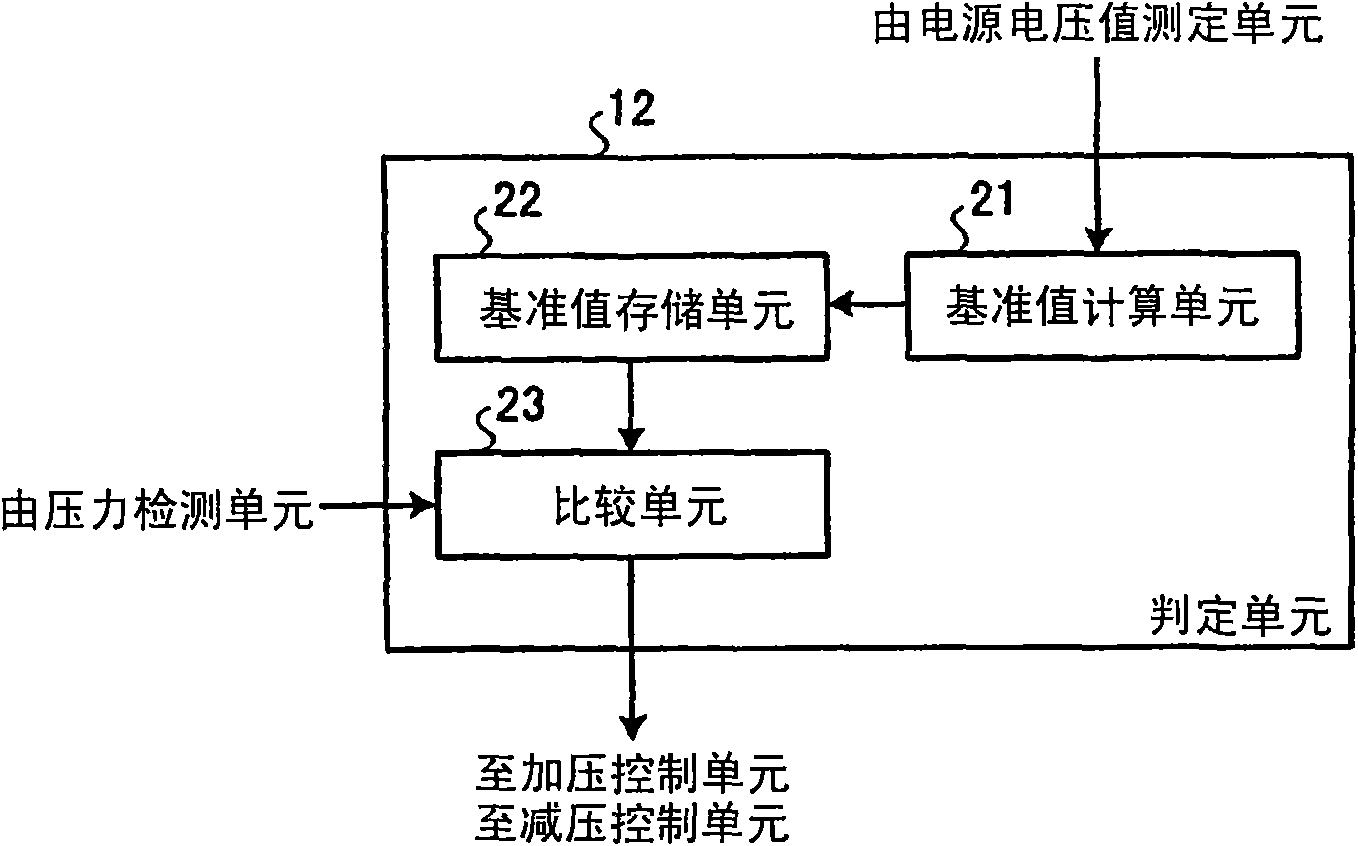
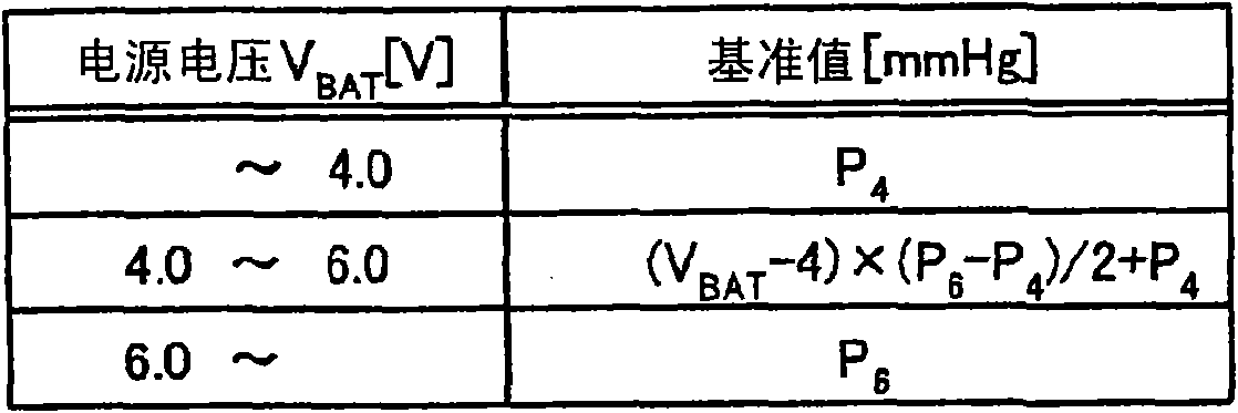
[0032] Driving voltages for the pressurization unit 3 and the decompression unit 4 are supplied from a power supply 9 . The power source 9 is constituted by a battery. Here, for example, assume a case where four dry batteries having a nominal voltage (nominal voltage) of 1.5 volts are connected in series. Furthermore, the electronic sphygmomanometer incorporates a regulator 10 for stepping down the power supply voltage of the...
Embodiment approach 2
[0061] The electronic sphygmomanometer of Embodiment 1 is an electronic sphygmomanometer that measures blood pressure while the cuff 1 is being decompressed at a slight speed, but the electronic sphygmomanometer of Embodiment 2 is an electronic sphygmomanometer that measures blood pressure while the cuff 1 is being pressurized. Therefore, the configuration of the electronic sphygmomanometer of Embodiment 2 differs from the configuration of the electronic sphygmomanometer of Embodiment 1 in the following points. In addition, the same reference numerals are assigned to the same configurations as in Embodiment 1, and overlapping descriptions are omitted.
[0062] Figure 8 It is a block diagram showing the overall configuration of the electronic sphygmomanometer according to Embodiment 2 of the present invention. Such as Figure 8 As shown, in the electronic sphygmomanometer of the second embodiment, the rapid exhaust unit 41 is provided as a decompression unit instead of the d...
PUM
 Abstract
Description
Claims
Application Information
 - R&D Engineer
- R&D Manager
- IP Professional
- Industry Leading Data Capabilities
- Powerful AI technology
- Patent DNA Extraction
Browse by: Latest US Patents, China's latest patents, Technical Efficacy Thesaurus, Application Domain, Technology Topic, Popular Technical Reports.
© 2024 PatSnap. All rights reserved.Legal|Privacy policy|Modern Slavery Act Transparency Statement|Sitemap|About US| Contact US: help@patsnap.com


