Detection device and detection method for state of relay contact in automotive high voltage circuit
The technology of a state detection device and high-voltage circuit is applied in the field of automobile manufacturing, which can solve the problems of wasting electric energy, unwarranted power consumption, affecting the power performance and fuel economy of the whole vehicle, and achieves the effect of reducing potential safety hazards and having a simple structure.
- Summary
- Abstract
- Description
- Claims
- Application Information
AI Technical Summary
Problems solved by technology
Method used
Image
Examples
Embodiment 1
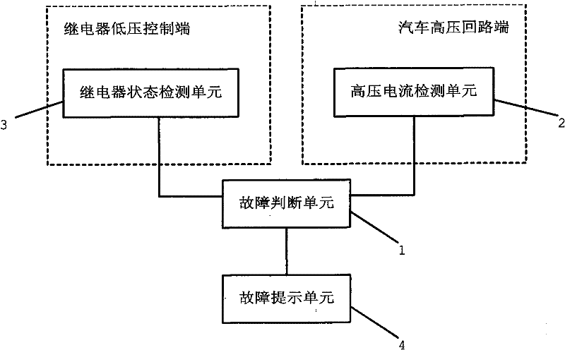
[0022] like figure 1 As shown, the relay contact state detection device of this embodiment includes a power supply circuit (not shown in the figure), a fault judgment unit 1, a high-voltage current detection unit 2 for detecting the high-voltage loop current of the automobile, and a high-voltage current detection unit 2 for detecting the pull-in state of the relay. The relay state detection unit 3 and the failure prompt unit 4 for prompting the failure situation, the high-voltage current detection unit 2 is located at the high-voltage circuit end of the automobile, the relay state detection unit 3 is located at the low-voltage control end of the relay, the high-voltage current detection unit 2, The relay state detecting unit 3 and the fault prompting unit 4 are electrically connected to the fault judging unit 1 respectively.
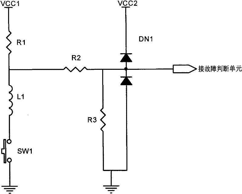
[0023] The fault judgment unit 1 receives signals from the high-voltage current detection unit 2 and the relay state detection unit 3, and judges the st...
Embodiment 2
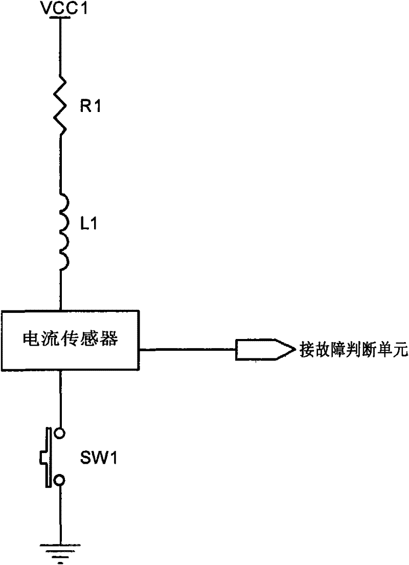
[0033] The difference from Embodiment 1 is that the relay state detection unit 3 in this embodiment is a relay current sensor connected in series in the relay low-voltage control circuit. The current sensor is connected in series with the relay coil. When the current sensor detects that there is current passing through, that is It means that the relay is closed; similarly, when there is no current passing through the current sensor, it means that the relay is off. In this way, by detecting the relay coil current, it can also be judged whether the relay is closed.
[0034] The specific judgment steps in this embodiment are the same as those in Embodiment 1.
Embodiment 3
[0036] like image 3 As shown, different from Embodiments 1 and 2, the relay state detection unit 3 in this embodiment is a relay current detection unit composed of a current sensor connected in series with a coil L2 arranged next to the relay and capable of coupling the current of the relay coil L1. circuit, resistor R4 is a current limiting resistor. When the relay is closed, the coil L2 in the relay current detection circuit will also generate current due to the coupling effect; when the relay is disconnected, no current will flow through the coil L2 in the relay current detection circuit. In this way, whether the relay is pulled in or not can be judged by using the current sensor to detect the current in the coil L2 connected in series with it.
[0037] The specific judgment steps in this embodiment are the same as those in Embodiment 1.
PUM
 Abstract
Description
Claims
Application Information
 - R&D Engineer
- R&D Manager
- IP Professional
- Industry Leading Data Capabilities
- Powerful AI technology
- Patent DNA Extraction
Browse by: Latest US Patents, China's latest patents, Technical Efficacy Thesaurus, Application Domain, Technology Topic, Popular Technical Reports.
© 2024 PatSnap. All rights reserved.Legal|Privacy policy|Modern Slavery Act Transparency Statement|Sitemap|About US| Contact US: help@patsnap.com


