
Absolute coding raster phase subdivision method based on charge coupling device

A charge-coupled device, absolute coding technology, applied in instruments, optical devices, measuring devices, etc., can solve the problems of limited measurement range and complex optical system of the reading head, and achieve the effect of improving resolution and measurement accuracy

Active Publication Date: 2009-11-04
CHENGDU QIANJIA TECH CO LTD
View PDF0 Cites 8 Cited by
  • Summary
  • Abstract
  • Description
  • Claims
  • Application Information

AI Technical Summary

Problems solved by technology

However, the value of n should not be too large. If the value of n is too large, firstly, the requirement for the number of pixels of the CCD will be very high; secondly, the optical system of the reading head will become complicated; thirdly, the measurement range will be limited

Method used


Image

  • Absolute coding raster phase subdivision method based on charge coupling device
  • Absolute coding raster phase subdivision method based on charge coupling device
  • Absolute coding raster phase subdivision method based on charge coupling device

Examples


Embodiment Construction

[0025] The CCD-based absolute encoding grating phase subdivision method of the present invention will be further described below through embodiments in conjunction with the accompanying drawings.

[0026] 1. Design of absolute coding grating

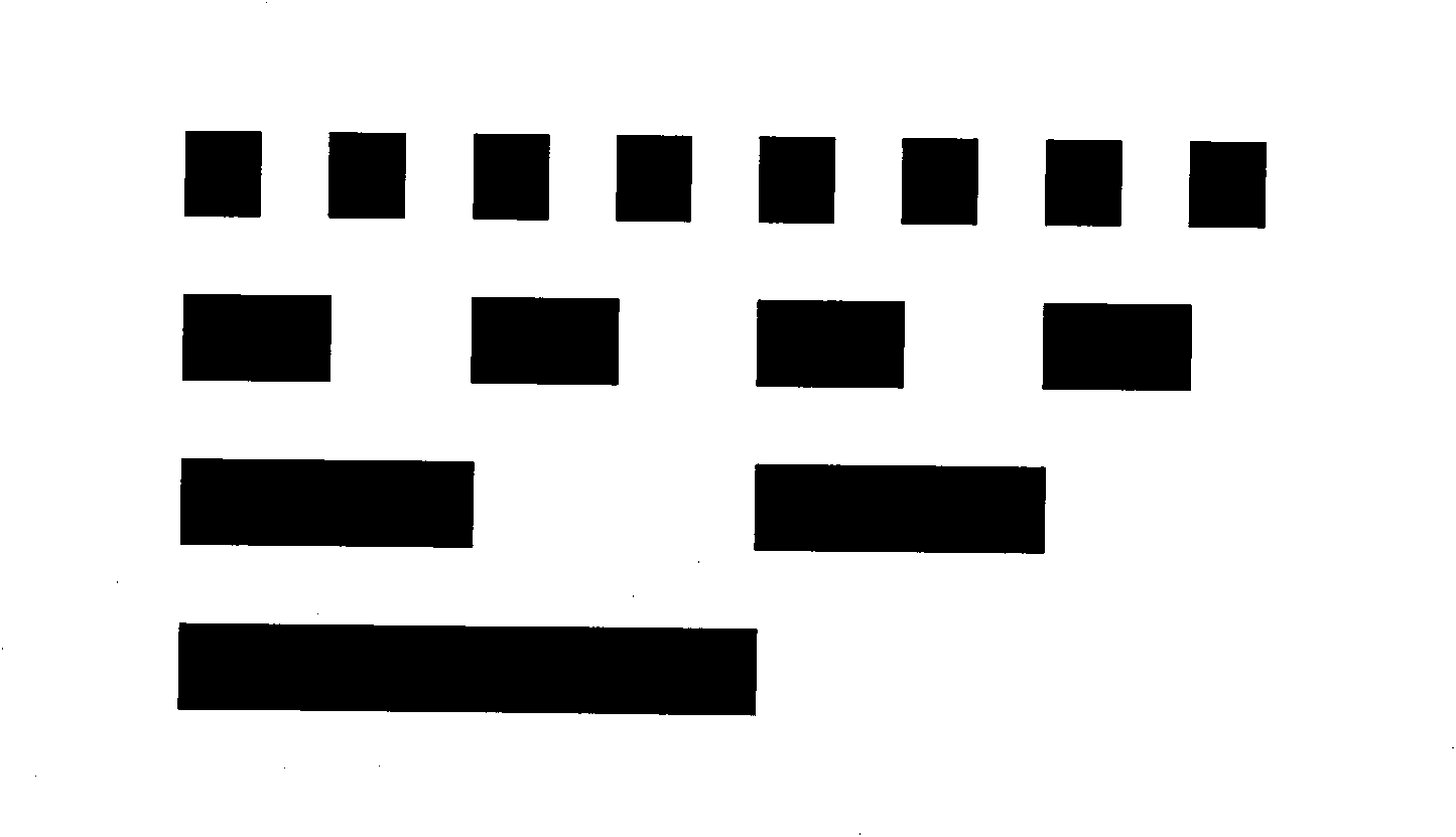
[0027] Absolutely coded gratings using natural binary codes, the structure of which is as follows figure 1 As shown, the minimum code channel unit graphic size is 1.5mm×1.5mm.

[0028] 2. Use the CCD reading head to read the code track pattern of the absolute coded grating

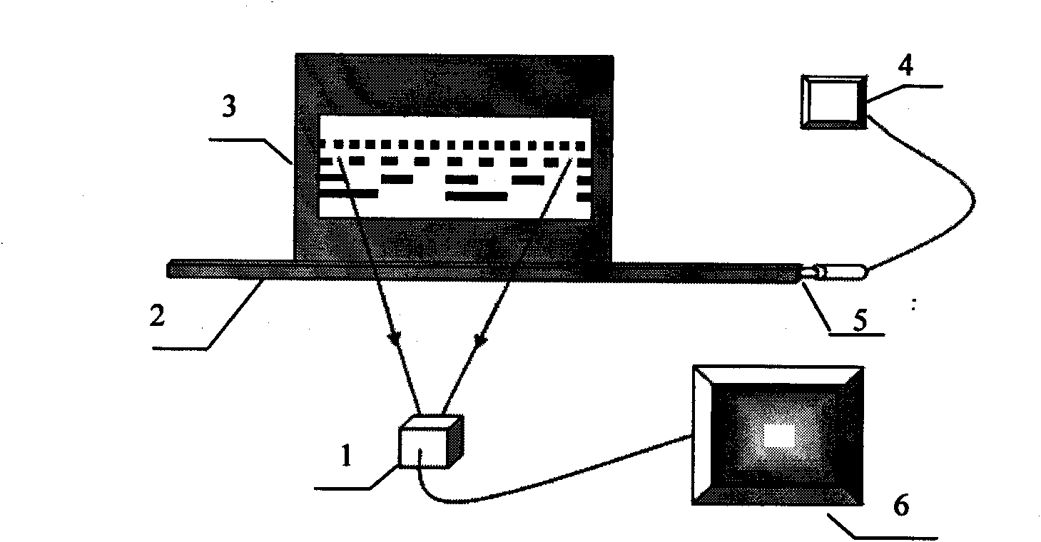
[0029] Use the CCD reading head to read the code track pattern of the absolute coded grating figure 2 As shown in the system, the system includes a CCD (800×600 pixel target surface) 1, a micro-movement stage 2, and an absolute coding grating ( figure 1 Shown) mobile plate 3, digital display instrument 4, micrometer head 5 and computer 6; The signal output end is connected to the digital display 4 through wires, the reading head of the CCD is installed against t...


PUM


Abstract

An absolute coding raster phase subdivision method based on a charge coupling device (CCD for short) is disclosed, comprising the following sequential steps of: (1) reading code channel graphics of the absolute coding raster with a CCD reading head; (2) subjecting a periodical discrete space function sequence formed by a row of the lowest code channel graphics in the obtained code channel graphics of the absolute coding raster to Flourier conversion so as to result in spectral distribution thereof; (3) taking out a fundamental component of the spectral distribution obtained in the step (2); (4) subjecting the obtained fundamental component to inverse Flourier conversion so as to result in a fundamental wave signal and a phase thereof; (5) generating the obtained fundamental wave signal in step (4) into a continuous phase by using N periodical phases; (6) expressing measurement resolution of the lowest code channel graphics in the absolute coding raster by using the average of the continuous phase. Such a method can realize the subdivision of pixels and remarkably enhance resolution and measurement accuracy of the absolute coding raster.

Description

technical field [0001] The invention belongs to the field of photoelectric measurement, in particular to a method for subdividing the minimum reference pattern—the lowest code path pattern in an absolute code grating. Background technique [0002] The photoelectric displacement precision measurement technology has the characteristics of high resolution, high precision, and high stability. Compared with the grating Moiré fringe technology, the absolute coding grating has many advantages: since it has a corresponding code value at any point, there is no cumulative error ; Larger linear displacements can be measured due to the large coding range. According to the characteristics of the absolute coded grating, its measurement range can theoretically exceed 100 meters, while the accuracy can still be maintained at the micron level. [0003] When using an absolute coded grating for displacement measurement, a charge-coupled device (CCD for short, hereinafter "CCD" is used to indi...

Claims


Application Information

Patent Timeline
Patent Type & Authority Applications(China)
IPC IPC(8): G01B11/02
Inventor 赵勇苏显渝李雯
Owner CHENGDU QIANJIA TECH CO LTD
Learn More