Flame shaping method for side bending deformation of transformer core clamping piece
A technology of iron core clips and transformers, applied in the field of flame shaping, can solve problems such as labor-intensive, poor correction effect, and time-consuming, and achieve the effect of solving side bending deformation, good shaping effect, and simple and easy method
- Summary
- Abstract
- Description
- Claims
- Application Information
AI Technical Summary
Problems solved by technology
Method used
Image
Examples
Embodiment 1
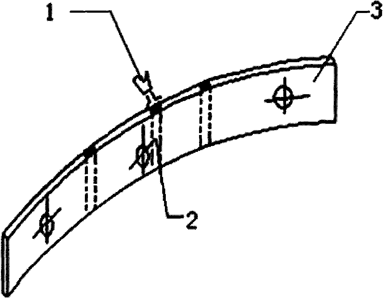
[0024] Embodiment 1 (see figure 1 ):
[0025] The flame shaping method for the side bending deformation of the plate core clamp is as follows:
[0026] The linear heating method is adopted for the splint 3 of the plate-type iron core clamp, that is, vertical linear heating zones 2 that are equal to each other are adopted, and at the same time, horizontal swing heating is performed in the width direction of the vertical linear heating zone 2, and the vertical linear heating The width of the zone 2 is 0.5-2 times the height of the splint 3;
[0027] If heating once fails to meet the shaping requirements, repeat heating is performed, and the repeated heating part is staggered from the previous heating part.
Embodiment 2
[0028] Embodiment 2 (referring to Fig. 2):
[0029] The shaping method for the sidebending deformation directed to the non-core side of the web is as follows:
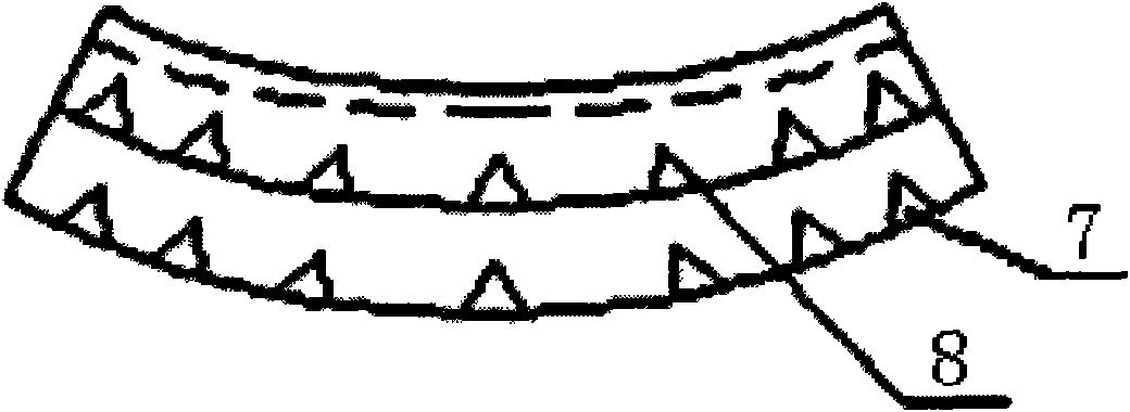
[0030] When the side bending deformation points to the non-core side of the web, the heating method of the triangular heating zone is respectively performed on the upper and lower limb plates of the clamp;
[0031] The triangular heating zone is a row of triangular heating zones, which are respectively located at the outer edges of the upper and lower limb plates, that is, the non-core side of the web, and the apex heights of the triangular heating zones are respectively greater than 1% of the width of the upper and lower limb plates. / 2, the bottom edge of the triangular heating zone is the outer edge of the upper and lower extremity plates; concentrated heating to 700-800 ° C, that is, the heated area is dark red;
[0032] If heating once fails to meet the shaping requirements, repeat heating is performed, and the r...
Embodiment 3
[0033] Embodiment 3 (see image 3 ):
[0034] The shaping method for the side bending deformation on the core side directed to the web is as follows:
[0035] When the side bending deformation points to the iron core side of the web, the upper and lower limb plates of the clamp are respectively heated in a triangular heating zone; at the same time, the web of the clamp is heated in a vertical linear shape;
[0036] The triangular heating area is a row of triangular heating areas, which are respectively located at the edges of the upper and lower limb plates near the web. The bottom edge of the triangular heating zone is the boundary between the upper and lower limb plates and the web plate; concentrated heating to 700-800 ° C, that is, the heated area is dark red;
[0037] The vertical linear heating of the web, that is, the vertical linear heating area corresponds to the triangular heating area located on the upper and lower limb plates, and the concentrated heating is 700-...
PUM
 Abstract
Description
Claims
Application Information
 - R&D Engineer
- R&D Manager
- IP Professional
- Industry Leading Data Capabilities
- Powerful AI technology
- Patent DNA Extraction
Browse by: Latest US Patents, China's latest patents, Technical Efficacy Thesaurus, Application Domain, Technology Topic, Popular Technical Reports.
© 2024 PatSnap. All rights reserved.Legal|Privacy policy|Modern Slavery Act Transparency Statement|Sitemap|About US| Contact US: help@patsnap.com


