Test device for concrete solar energy collection, snow melt and deicing

A technology of solar heat collection and test device, applied in the field of test device

Active Publication Date: 2011-01-12
武汉理工大产业集团有限公司
View PDF0 Cites 1 Cited by
  • Summary
  • Abstract
  • Description
  • Claims
  • Application Information

AI Technical Summary

Problems solved by technology

However, whether it is solar heat collection or road surface snow melting and ice melting, there is no unified simulation test device in China to test the heat collection performance and the efficiency of snow melting and ice melting

Method used


Image

  • Test device for concrete solar energy collection, snow melt and deicing
  • Test device for concrete solar energy collection, snow melt and deicing
  • Test device for concrete solar energy collection, snow melt and deicing

Examples


Embodiment 1

[0042] Example 1: Experimental device for concrete solar heat collection and snow melting and ice melting

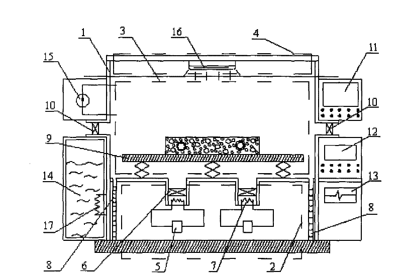
[0043] The structure of the device is as figure 1 Shown: It consists of a control cabinet, an auxiliary box and a test box 1 between them. The test box 1 is composed of a motor cabinet 2, a sample cabinet 3 and a solar light cabinet 4 arranged in sequence from bottom to top in its inner cavity, and a second fan 10 is provided on both sides thereof. The motor cabinet 2 is mainly provided with an air compressor 5 , a first fan 6 , a heat exchanger 7 and a drainage pipe 8 . The sample cabinet 3 is equipped with a liftable test bench 9, whose height can be adjusted within a certain range, so that the surface of the sample is parallel to the air outlet of the second fan 10 to simulate the ambient wind during the test. The solar light cabinet 4 adopts a water-cooled full solar spectrum long-arc xenon lamp 16 . The control cabinet is equipped with a test data acquisition and...

Embodiment 2

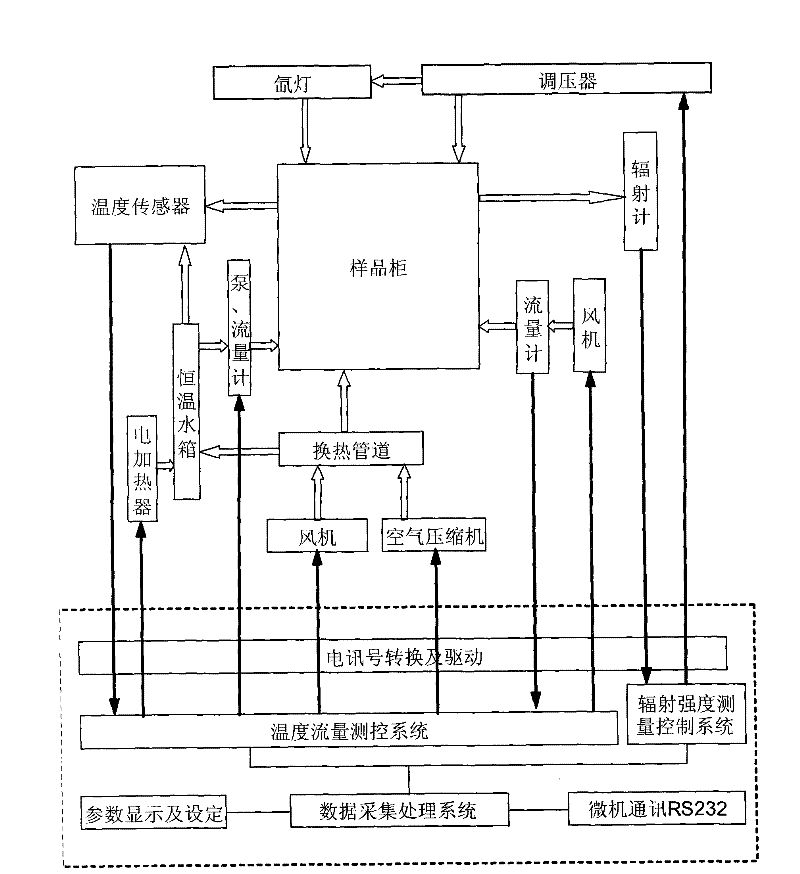
[0047] Embodiment 2: illustrate the control flowchart of the present invention in conjunction with accompanying drawing

[0048] like figure 2 As shown: the temperature sensor adopts a two-wire or four-wire thermal resistance, the temperature measurement of the test box 1 and the constant temperature water tank 14 uses a two-wire thermal resistance, and the measurement of the sample temperature field adopts an industrial grade II four-wire thermal resistance. After the signal obtained by the temperature sensor is transmitted to the temperature flow measurement and control system, the data of the sample is further processed and recorded; after the temperature data of the test box 1 and the constant temperature water tank 14 are judged, the electrical signal is fed back to the air compressor 5 and the first fan 6 And heat exchanger 7, the temperature in the test box body is adjusted to test requirement, also can control the electric heater 17 of constant temperature water tank ...

Embodiment 3 and Embodiment 4

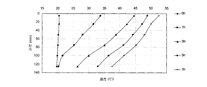
[0049] Embodiment 3 and embodiment 4: solar heat collection test


PUM


Abstract

The invention relates to a test device for concrete solar energy collection, snow melt and deicing, which consists of a control cabinet, an auxiliary box and a test box body (1). An inner cavity of the test box body is provided with a motor cabinet (2), a sample cabinet (3) and a solar lamp cabinet (4) which are arranged from the bottom to top, and two sides of the test box body are provided withsecond blowers (10); a lifting sample stage (9) is arranged in the sample cabinet, and the height of the lifting sample stage can be adjusted within a definite range to make the surface of a sample parallel to an air opening of the second blower to simulate environmental air during test; the control cabinet is provided with a test data acquisition processing system (11), a temperature-flow measuring and controlling system (12) and a radiation intensity measuring and controlling system (13) which are connected by data wires; and the auxiliary box is provided with a thermostatic water tank (14)and a metering pump (15) which are connected by a pipeline. The test device can carry out asphalt concrete solar energy collection test under various environments, and also can carry out concrete snowmelt and deicing test of an electric heating method and a thermal fluid method.

Description

technical field [0001] The invention relates to a test device, in particular to a test device for solar heat collection and snow melting and ice melting by using asphalt concrete roads. Background technique [0002] In recent years, the energy shortage at home and abroad has become increasingly tense. At the same time, the greenhouse effect and environmental pollution caused by the use of fossil fuels have made it imperative to develop and utilize renewable energy. Solar thermal utilization is one of the main technical approaches at present. Heat collection is an important part of solar heat utilization technology. Heat collection materials are the key to solar heat collection systems. The absorption performance of heat collection materials for sunlight determines the quality of the entire heat collection system. Asphalt concrete takes advantage of its high absorption rate of the solar spectrum, and asphalt pavement is like a huge solar absorbing panel. If the heat collecte...

Claims


Application Information

Patent Timeline
Patent Type & Authority Patents(China)
IPC IPC(8): G01M99/00
Inventor 吴少鹏陈明宇张园王虹陈筝韩君米轶轩林俊涛
Owner 武汉理工大产业集团有限公司
Why Eureka
Try Eureka