
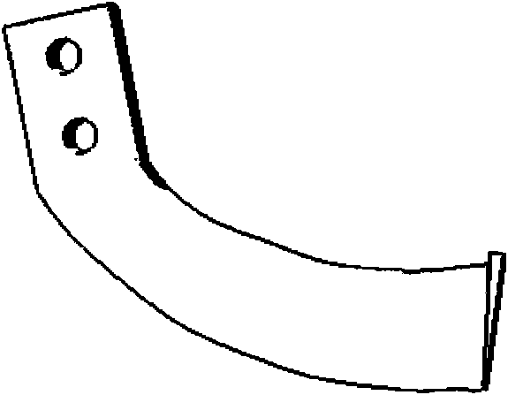
Cultivation rotation working part with bionic geometric structure

A technology of rotating work and geometric structure, applied in the field of farming rotating working parts and farming machinery design, can solve the problems of increasing energy consumption, machinery can not work, increasing working resistance, etc., achieving low energy consumption, low soil cutting resistance, The effect of low power consumption

Inactive Publication Date: 2009-10-07
JILIN UNIV
View PDF0 Cites 20 Cited by
  • Summary
  • Abstract
  • Description
  • Claims
  • Application Information

AI Technical Summary

Problems solved by technology

[0003] When agricultural machinery is working, the adhesion phenomenon caused by the contact between the surface of the soil-contacting parts and the soil will increase the working resistance, reduce the working efficiency and working quality, increase energy consumption, and increase the disturbance and damage to the soil at the same time, causing the soil to lose moisture Severe, even make the machine unable to work

Method used


Image

  • Cultivation rotation working part with bionic geometric structure
  • Cultivation rotation working part with bionic geometric structure
  • Cultivation rotation working part with bionic geometric structure

Examples


Embodiment 1

[0031] In this example, the specific structure of the new farming rotary working part with bionic geometry is given by image 3 and Figure 4 show. The structural feature of the novel tillage rotating part of this example is: the tangential section of the blade is triangular when seen from the side, which is different from the rectangular section of the traditional blade. There is a bionic arc cutting edge distributed on the cutting edge of the blade, the directions are facing inward and outward respectively, the chord length is fixed to the blade width L, which is 60mm, and the center angle of the round edge can be adjusted, corresponding to the change of the center angle or half circle As the (straight) diameter changes, the size of the bionic cutting edge also changes.

Embodiment 2

[0033] In this example, the specific structure of the new farming rotary working part with bionic geometry is given by Figure 5 and Figure 6 show. The new type of farming rotary working part with bionic geometric shape described in this example is different from Example 1 in that the tangential side view of the blade in this example is triangular, and the tangent edge is evenly distributed with 2 bionic arc cutting edges facing inward (outward). , the chord length is L / 2, that is, 30mm, if the corresponding center angle or the semi-(straight) diameter of the arc changes, the size of the two bionic cutting edges will also change accordingly.

Embodiment 3

[0035] In this example, the specific structure of the new farming rotary working part with bionic geometry is given by Figure 7 and Figure 8 show. The new farming rotary working part with bionic geometry described in this example differs from Example 1 and Example 2 in that the tangential side view of the blade in this example is triangular, and the tangential edges are evenly distributed with 3 bionic inwards (outwards) The chord length of the arc cutting edge is L / 3, that is, 20mm. The size of the bionic cutting edge is determined by the corresponding central angle or semi (diameter) diameter.


PUM


Abstract

The present invention relates to a geometric structure of rotation working part of used for driving type rototilling-tillage machine, and especially to a cultivation rotation working part with bionic geometric structure. The invention takes the fore leg claw toe of mole with high-efficient digging capability as a bionic researching object, extracts the special geometric structure characteristic and applies the geometric structure characteristic for designing the rotation working parts (rotary blade or stubble breaking blade) on the cultivation machinery. The component is mainly composed of a side cutting surface with a side cutting edge, a front cutting surface with positive cutting blade, a transition surface for connecting the front cutting surface and the side back surface, and a transition edge for connecting the front cutting edge and the side cutting edge. The invention is characterized in that the front cutting edge (6) adopts a bionic circular arc structure. The geometric shape is confirmed by the following equation: when the operation breadth of single blade of front cutting edge is L, the corresponding central angle of circular cutting edge is (theta), the corresponding radius is (r), and the number of circular arcs is (n), the corresponding expression is as follows: L / 2nr=sin(theta / 2). The cultivation rotation working part with bionic geometric structure according to the invention can greatly reduce the energy consumption in cultivation operation under the precondition that the cultivation quality is ensured.

Description

Technical field: [0001] The invention relates to a geometric structure of a rotary working part for a driving type tillage and land preparation machine, in particular to a rotary working part for tillage with a bionic geometric structure, which belongs to the design technology of tillage machinery in agricultural machinery. Background technique: [0002] A rotary tiller is a tillage machine that shreds soil by power-driven working parts. It uses the compound movement of the rotation and forward movement of the blade on the cutter shaft to crush the uncultivated land and the cultivated land. Its performance is characterized by its strong ability to crush soil. One rotary tillage can achieve the effect of ordinary plows several times. After rotary tillage The fields can meet the requirements of sowing or transplanting. The rotary tiller has good working quality and high work efficiency. It can not only save time for farming, save labor, but also reduce the number of times the...

Claims


Application Information

Patent Timeline
Patent Type & Authority Applications(China)
IPC IPC(8): A01B33/10
Inventor 佟金汲文峰马云海贾宏雷陈东辉孙雯宇周江常志勇
Owner JILIN UNIV
Learn More