
Door lock apparatus

A technology for door locks and car doors, which is applied in the field of door lock devices with a stop mechanism, which can solve the problems of large-scale door lock devices and large-scale inner joysticks, etc., and achieve the effect of improving operability

Inactive Publication Date: 2012-07-18
MITSUI KINZOKU ACT
View PDF3 Cites 0 Cited by
  • Summary
  • Abstract
  • Description
  • Claims
  • Application Information

AI Technical Summary

Problems solved by technology

However, in the conventional door lock device, the size of the door lock device may be increased due to the difference in the arrangement of the inside lever.
That is, since the connecting rod and the fan-shaped lever are swung by the swing of the inner stick, according to this arrangement, there is a possibility that the size of the inner stick may be increased.

Method used


Image

  • Door lock apparatus
  • Door lock apparatus
  • Door lock apparatus

Examples


Embodiment approach 1

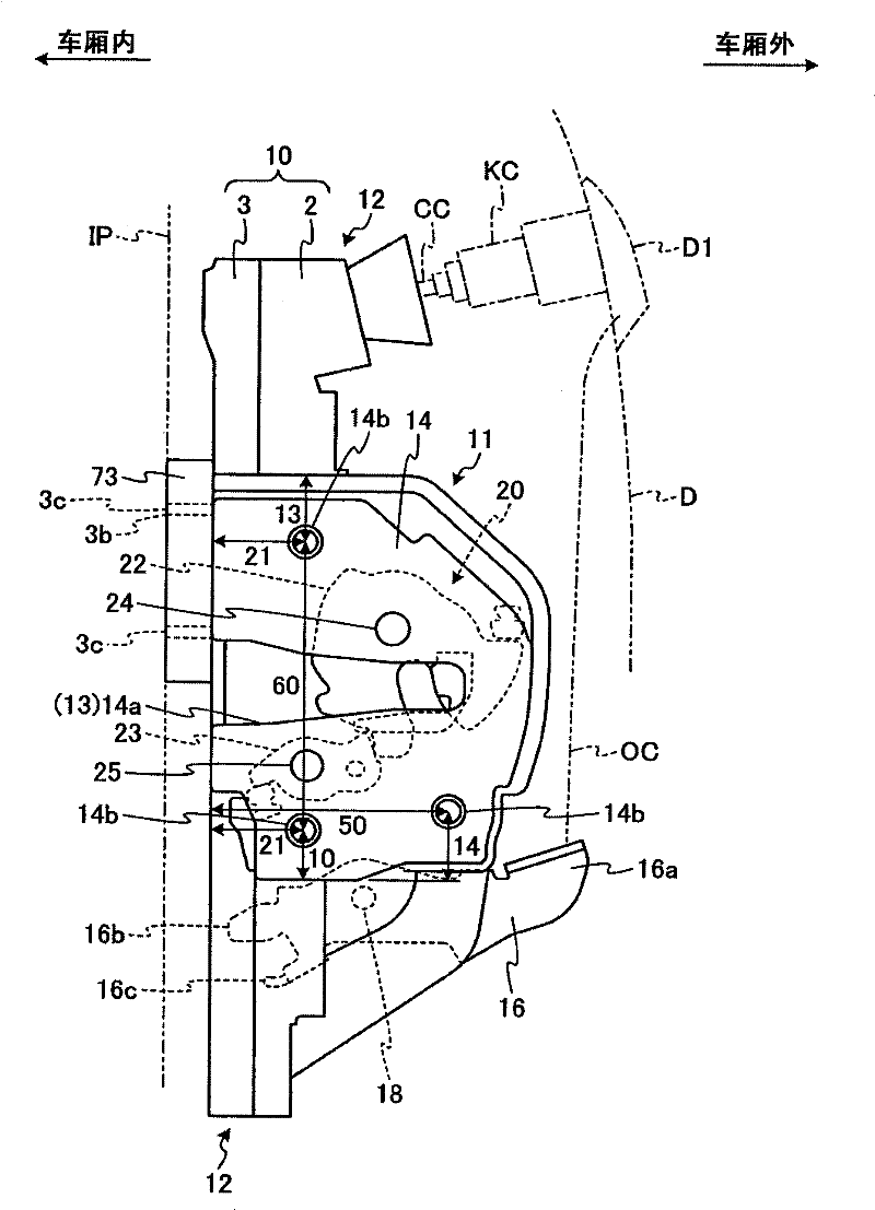
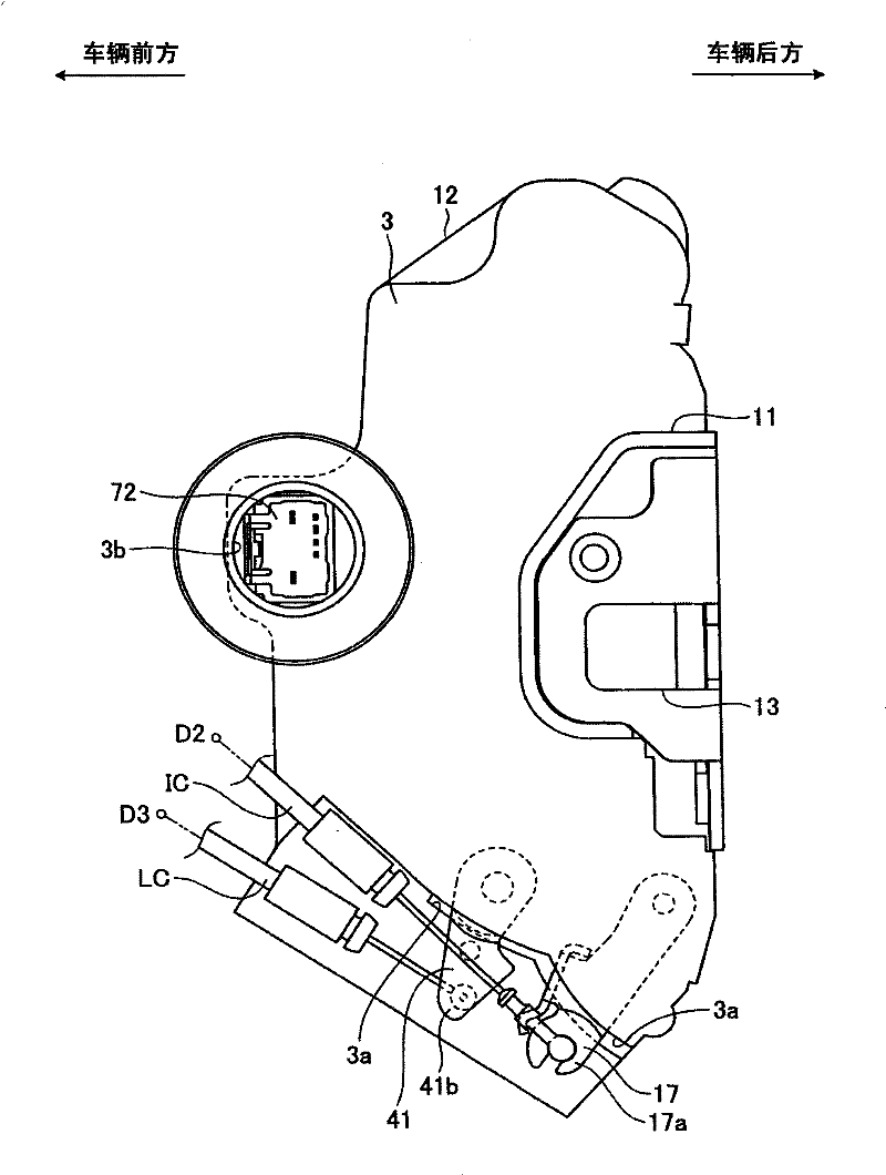
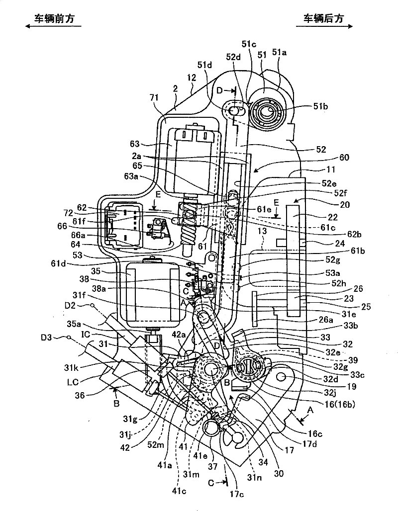
[0177] figure 1 as well as figure 2 It is a view showing a door lock device according to Embodiment 1 of the present invention, image 3 for expressing in figure 1 View of the door lock unit shown with the sub-housing removed. The door lock device exemplified here is provided on a front hinged side door disposed on the front right seat of a four-wheeled motor vehicle (the door D on the side of the driver's seat in a vehicle with a right-hand steering wheel), and includes a main housing 2 and a Sub shell 3.

[0178] The main housing 2 and the sub housing 3 are each formed of, for example, a synthetic resin material, and after they are joined to each other, they are connected to each other by a fastening means (not shown) such as bolts, thereby constituting the bracket 10 . In addition, a gasket member (not shown) is used at the junction of the main case 2 and the sub case 3 to ensure desired watertightness.

[0179] The bracket 10 composed of the main case 2 and the sub-c...

Embodiment approach 2

[0255] Figure 23 It is a view of the door lock device according to the second embodiment of the present invention when the sub-housing is removed and viewed from the interior of the vehicle compartment. The door lock device in the second embodiment differs from the door lock device in the first embodiment above in that it does not have a lock lever, a double lock mechanism, and an electric motor for driving them, as well as in the structure of the sector lever. Differences, other configurations are the same as those in Embodiment 1. Below, these differences are described in detail. In addition, the same reference numerals are assigned to the same structures in Embodiment 2 as those in Embodiment 1, and descriptions thereof are omitted.

[0256] The fan lever 131 is provided at a position closer to the front of the vehicle than the opening lever 16, and can be swung by a fan lever shaft 34 extending substantially horizontally in the left-right direction of the vehicle body, ...


PUM


Abstract

A door lock apparatus capable of improving operability without large-scale. The door lock apparatus, at both sides of a region interposing a second link lever (33) therebetween, includes a sector lever shaft (34) and an inside lever shaft (19) that extend in parallel with a swinging shaft of the second link lever (33). The door lock apparatus also includes an inside handle lever (17) swingably arranged about the inside lever shaft (19), and when an inside door handle (D2) arranged inside a vehicle is open-operated while the second link lever (33) is disposed in a cancel position, moves the second link lever (33) upwards by swinging about the center of the inside lever shaft (19), and when the inside door handle (D2) is open-operated while the second link lever (33) is disposed in a non-cancel position, swings the sector lever (31) in a locked position to an unlocked position about the center of the sector lever shaft (34), by swinging about the center of the inside lever shaft (19).

Description

technical field [0001] The present invention relates to a door lock device suitable for vehicles such as four-wheel motor vehicles, and more particularly to a door lock device provided with a latch mechanism (Latch Mechanism) when the door is arranged in a closed position relative to the vehicle body When it becomes a stop state, the movement of the door in the opening direction is restricted. Background technique [0002] Conventionally, there has been a device including a connecting rod, a sector rod, and an inside lever in its construction among door lock devices. The connecting rod slides between the release position and the non-release position. When it is shaken in the state of being arranged in the release position, it will release the stop state of the stop mechanism, thereby allowing the door to move in the opening direction; the other On the one hand, when it is rocked in the state of being in the non-releasing position, the stopped state of the stop mechanism wil...

Claims


Application Information

Patent Timeline
Patent Type & Authority Patents(China)
IPC IPC(8): E05B65/20E05B83/36B60J5/00E05B77/30E05B79/08
CPCE05B77/30E05B85/26E05B81/16E05B85/06E05B17/041E05B77/283E05B77/28E05B81/06Y10T292/1076Y10T292/1043Y10T292/1047Y10T292/1082E05B77/22E05B85/00
Inventor 石黑克行多贺隆雄
Owner MITSUI KINZOKU ACT
Learn More