Electric-controlled permanent magnetic chuck

An electronically controlled permanent magnet and suction cup technology, which is applied in the direction of load hanging components, transportation and packaging, etc., can solve problems such as easy generation of residual magnetism, influence on suction force, and large power consumption, so as to expand the scope of use, improve suction efficiency, good effect

Inactive Publication Date: 2009-09-30
岳阳鸿升电磁科技有限公司
View PDF0 Cites 15 Cited by
  • Summary
  • Abstract
  • Description
  • Claims
  • Application Information

AI Technical Summary

Problems solved by technology

[0002] In the actual production process, the application of a variety of lifting electromagnets provides a very convenient service for industrial production, but once the electromagnet is powered off, a backup battery must be put in immediately to ensure safe work. Many devices and high power consumption are problems we must face
Although the use of permanent magnet hangers is safe and power-saving, they all use mechanical levers to work, and it is difficult to achieve arbitrary control
There are also many manufacturers of electro-permanent magnets, which have the following main characteristics: (1) The magnetic steel in the magnet is usually externally magnetic, and the reverse magnetic field generated by the coil winding is used to offset the magnetic field in the magnet for discharging when discharging. ; (2) Simple superposition of reversible magnets and irreversible magnets will easily lead to magnetic attenuation of irreversible magnets and affect the suction force, and residual magnetism will easily occur after a long working time; (3) It is not conducive to absorbing heavy objects with large air gaps

Method used


Image

  • Electric-controlled permanent magnetic chuck
  • Electric-controlled permanent magnetic chuck
  • Electric-controlled permanent magnetic chuck

Examples


Embodiment Construction

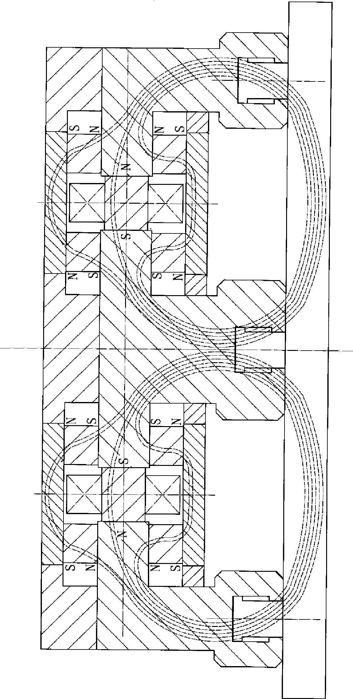
[0015] Depend on Figures 1 to 3 It can be seen that the present invention includes a coil, a magnetic steel, a yoke, and a magnetic pole, wherein:

[0016] The magnetic steel is composed of reversible magnetic steel 8 and irreversible magnetic steel 5. The reversible magnetic steel 8 is used in the main magnetic circuit, the coil 7 is arranged around the reversible magnetic steel 8, and the irreversible magnetic steel 5 is an auxiliary magnetic steel. side;

[0017] A yoke 3 is arranged on both sides of the reversible magnetic steel 8 and the irreversible magnetic steel 5, and the ends of the yoke 3 are connected to the magnetic pole 2;

[0018] The reversible magnetic steel 8, the coil 7, the yoke 3, the magnetic pole 2 and the attracted object 1 form the main magnetic circuit, and the irreversible magnetic steel 5 and the irreversible magnetic steel magnetic connection plate 6 form the auxiliary magnetic circuit;

[0019] The main magnetic circuit structure and the auxili...


PUM


Abstract

The invention relates to an electric-controlled permanent magnetic chuck, comprising a coil, a magnet steel, a magnet yoke and a permanent magnetic chuck of a magnetic pole, wherein the magnet steel is composed of a reversible magnet steel and a non-reversible magnet steel. The reversible magnet steel is used in a main magnetic circuit; the coil is arranged around the reversible magnet steel and the non-reversible magnet steel is arranged at two sides of the reversible magnet steel as the auxiliary magnet steel. The magnet yokes are arranged at two sides of the reversible magnet steel and the non-reversible magnet steel. The end of the magnet yoke is connected with the magnetic pole. The main magnetic circuit consists of reversible magnet steel, coil, magnet yoke, magnetic pole and sucked objects and the auxiliary magnetic circuit consists of the non-reversible magnet steel and the non-reversible magnet steel magnetic conduction connecting board. The main magnetic circuit structure and the auxiliary magnetic circuit are connected into an integral structure by a non-magnetic conductor. The invention is suitable for swinging a plurality of square billets and high-temperature square billets after heat insulating process. The mobile magnetic pole can greatly increase the suction efficiency for a long period application. The invention greatly expands the application range of the electric-controlled permanent magnetic chuck and provides a new way for the development of the hoisting electromagnet.

Description

technical field [0001] The invention relates to a lifting magnet, specifically refers to an electronically controlled permanent magnetic sucker that only absorbs and discharges the material in the process of transporting magnetic materials, and is controlled instantaneously by a power supply. Background technique [0002] In the actual production process, the application of a variety of lifting electromagnets provides a very convenient service for industrial production, but once the electromagnet is powered off, a backup battery must be put in immediately to ensure safe work. Many devices and high power consumption are problems we must face. Although the use of permanent magnet hangers is safe and power-saving, they all use mechanical levers to work, and it is difficult to achieve arbitrary control. There are also many manufacturers of electro-permanent magnets, which have the following main characteristics: (1) The magnetic steel in the magnet is usually externally magneti...

Claims


Application Information

Patent Timeline
Patent Type & Authority Applications(China)
IPC IPC(8): B66C1/06
Inventor 梁志军
Owner 岳阳鸿升电磁科技有限公司
Why Eureka
Try Eureka