
Method and equipment for automatically controlling press mounting of assembly part

A technology for assembly and press-fitting, which is applied in the field of automatic control press-fitting methods and equipment for assembled parts, can solve the problems of inconvenient judgment of whether the press-fitting force of a product is qualified, and achieve convenient technical analysis and later tracking, reliable transmission speed, and press-fitting. The effect of smooth installation process

Inactive Publication Date: 2009-09-23
FINETOP SCI &TECH
View PDF0 Cites 10 Cited by
  • Summary
  • Abstract
  • Description
  • Claims
  • Application Information

AI Technical Summary

Problems solved by technology

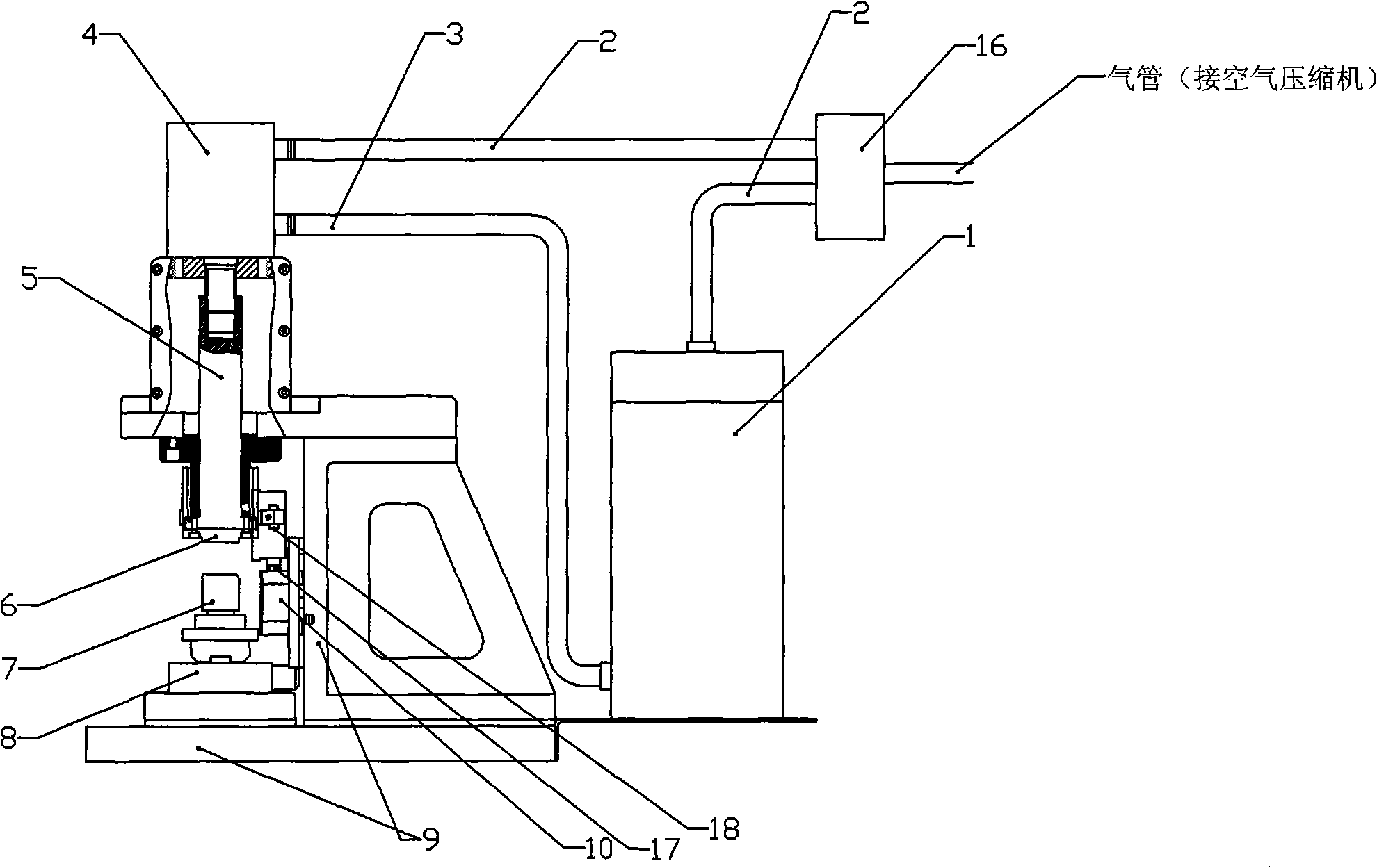
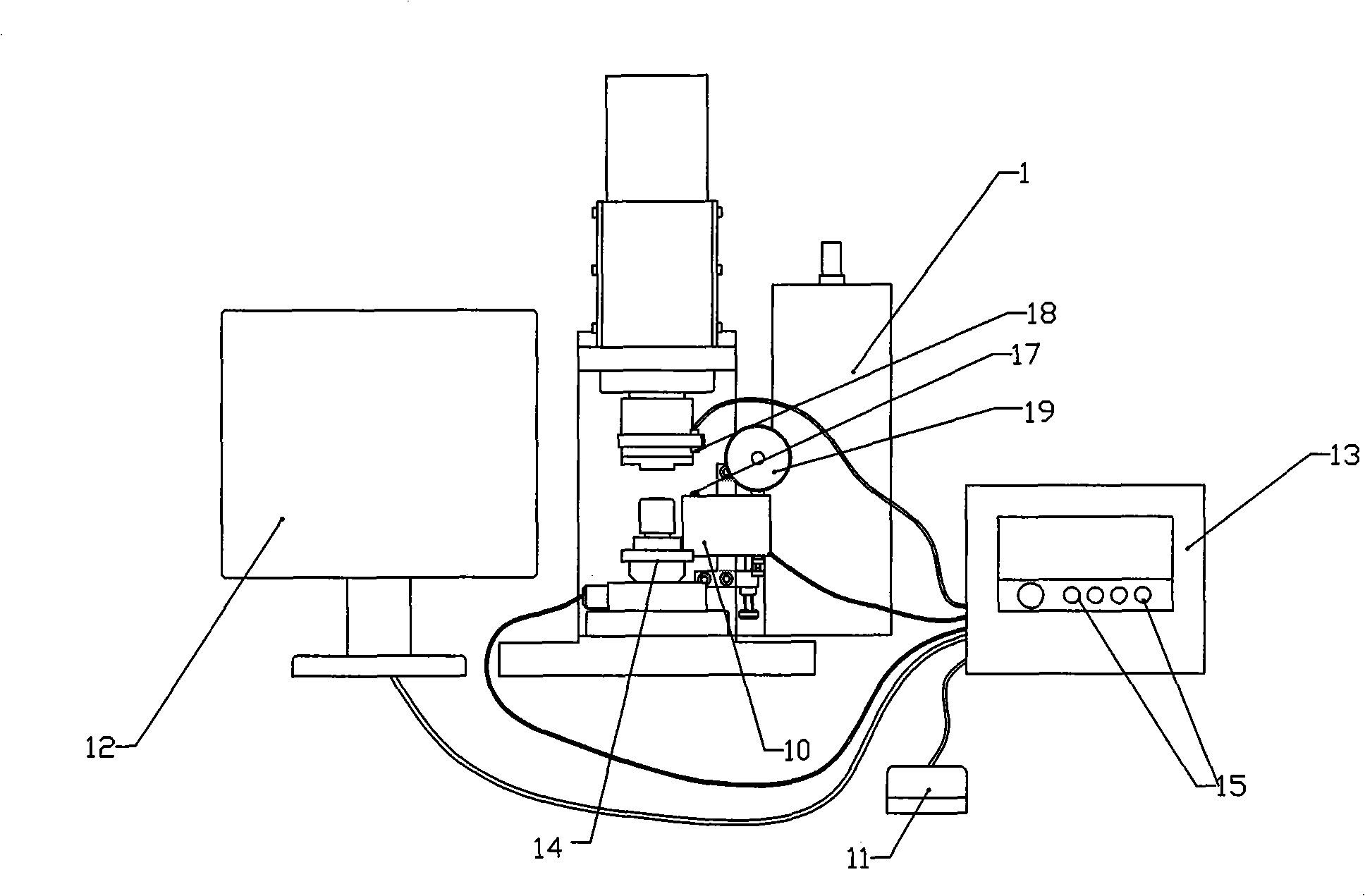
[0005] The purpose of the present invention is to provide an automatic control press-fit method for assemblies, aiming at solving the problem that the existing press-fit technology for optical transceiver components cannot enable the operator to accurately understand the pressure value when the components are pressed to a certain position. It is convenient for the operator to judge whether the product pressing force is qualified

Method used


Image

  • Method and equipment for automatically controlling press mounting of assembly part
  • Method and equipment for automatically controlling press mounting of assembly part
  • Method and equipment for automatically controlling press mounting of assembly part

Examples


Embodiment Construction

[0026] In order to make the objectives, technical solutions and advantages of the present invention clearer, the present invention will be further described in detail below with reference to the accompanying drawings and embodiments. It should be understood that the specific embodiments described herein are only used to explain the present invention, but not to limit the present invention.

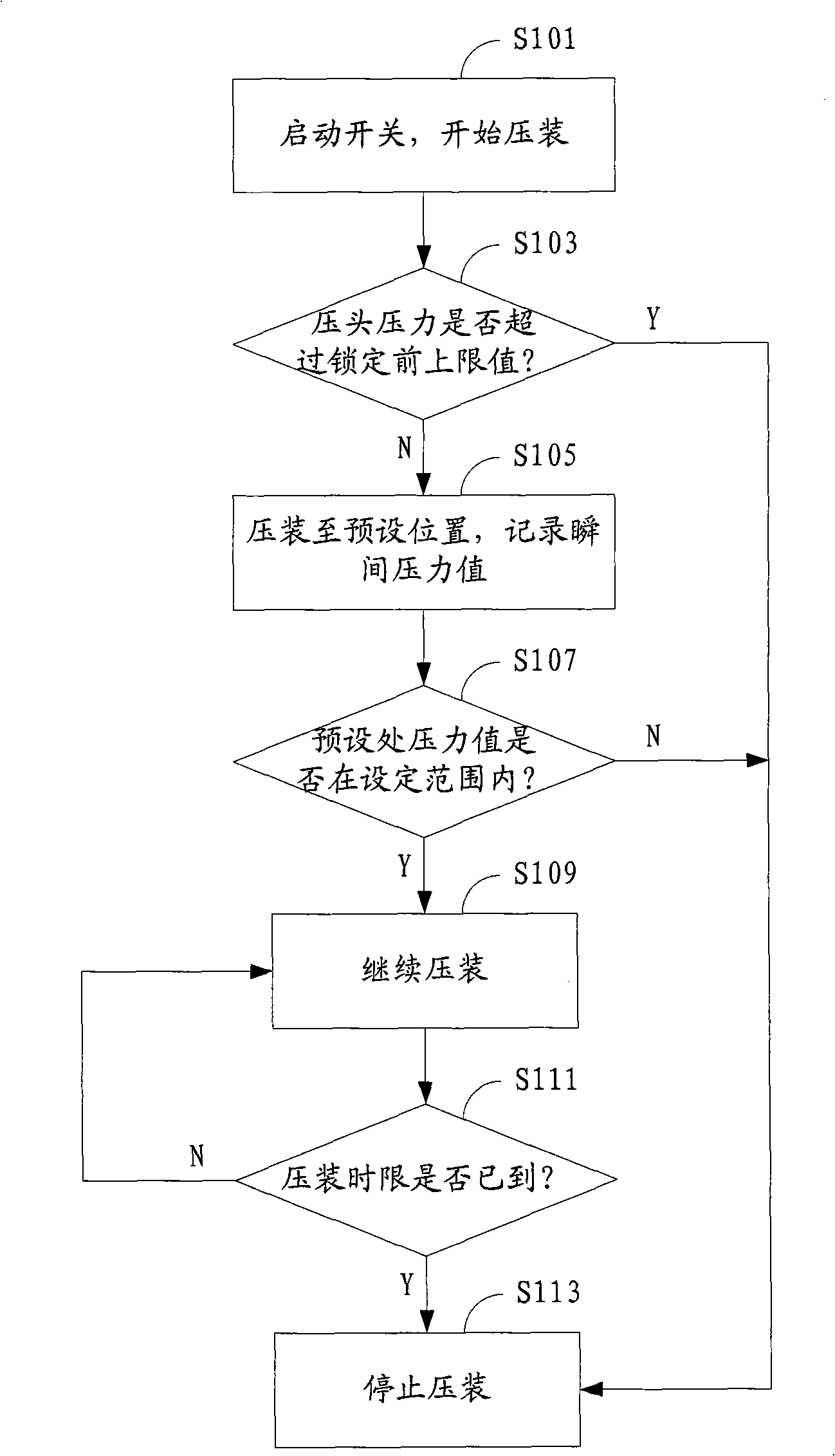
[0027] figure 1 The implementation process of the automatic control pressing method for the assembly provided by the embodiment of the present invention is shown, and the details are as follows:

[0028] In step S101, the switch is activated to automatically start press-fitting.

[0029] In step S103, before the indenter presses the workpiece to the preset position, the pressing force signal of the indenter is collected in real time and whether it exceeds the preset upper limit value before locking is detected in real time. If not, the indenter is controlled to continue Press-fit; if it ...


PUM


Abstract

The invention is suitable for the field of manufacturing optical active components and optical passive components in the optical communication technique, and provides a method and equipment for automatically controlling the press mounting of an assembly part. The method comprises: a switch is started to begin the process of press mounting; before a workpiece is pressed and mounted at a preset position by a pressure head, real-time collection of press mounting signal of the pressure head and detection that whether the press mounting signal exceeds a preset pre-locking upper limit value or not are carried out, if yes, press mounting is stopped immediately, if no, press mounting is continued; when the workpiece is pressed and mounted at the preset position by the pressure head, the instantaneously collected pressure value of the pressure head towards the workpiece is recorded and stored, and whether the pressure value is between a preset post-locking upper limit value and a post-locking lower limit value or not is judged; if yes, the press mounting is continued, if no, the press mounting is stopped immediately; and when the pressure head is downwards pressed, timing is started, and whether the counted time reaches the preset press mounting time limit or not is real time monitored in the process of press mounting, and if yes, the press mounting is stopped, if no, the press mounting is continued.

Description

technical field [0001] The invention belongs to the field of optical active and passive device manufacturing in the optical communication technology, and in particular relates to a method and equipment for automatic control and pressing of an assembly. Background technique [0002] During the assembly process of the optical transceiver, the core component of the optical transceiver module, some press-fitting processes are often involved, such as: press-fitting the short ferrule into the stopper of the metal part; press-fitting the stopper to the ferrule sleeve; Chips are press-fitted to metal housings; and so on. The size of the press-fitting force during the press-fitting process will directly affect the reliability of the product, so the press-fitting force is one of the conditions for judging whether the components are qualified after the press-fitting. Judging whether the pressing force is qualified or not. [0003] The existing press-fitting of components is usually r...

Claims


Application Information

Patent Timeline
Patent Type & Authority Applications(China)
IPC IPC(8): G02B6/42G02B6/38
Inventor 胡永忠罗祠富
Owner FINETOP SCI &TECH
Learn More