Lightning isolation device and lightning isolation method

An isolation device, lightning technology, applied in circuit devices, emergency protection circuit devices, emergency protection circuit devices for limiting overcurrent/overvoltage, etc. , equipment damage, etc.

Inactive Publication Date: 2012-05-30
HANGZHOU WANGCE COMM TECH
View PDF0 Cites 0 Cited by
  • Summary
  • Abstract
  • Description
  • Claims
  • Application Information

AI Technical Summary

Problems solved by technology

[0002] Every year, a large number of mobile communication base stations and repeaters are struck by lightning, most of which are induced lightning. The strong surge current is introduced into the base station or repeater and other equipment through the power supply line, causing equipment damage
Although there are various protection switches and grounding measures, they are basically passive lightning protection measures, which only work when they are struck by lightning. Since it takes time for these measures to work, many devices are still damaged by lightning every year.

Method used


Image

  • Lightning isolation device and lightning isolation method
  • Lightning isolation device and lightning isolation method
  • Lightning isolation device and lightning isolation method

Examples


Embodiment 1

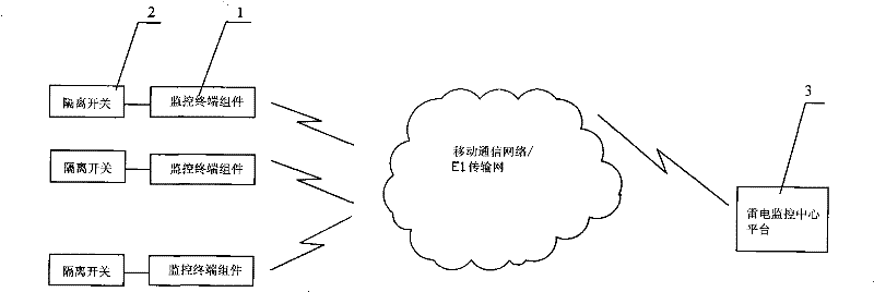
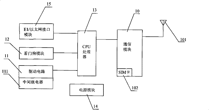
[0032] Embodiment 1, Figure 1 ~ Figure 3 In combination, a lightning isolation device is provided, including a lightning monitoring center platform 3, several monitoring terminal components 1 (in this embodiment, the number is 3) and isolation devices corresponding to each monitoring terminal component 1 one by one. switch 2.

[0033] Each monitoring terminal assembly 1 includes a communication module 10 containing a SIM card 102 , a drive circuit 11 , a watchdog module 12 , a CPU processor 13 , a power supply module 14 and an E1 / Ethernet interface module 15 . The power supply module 14 is connected with the communication module 10 , the driving circuit 11 , the watchdog module 12 , the CPU processor 13 and the E1 / Ethernet interface module 15 respectively. For the clarity of the figure, the figure 2 The above connection relationship is omitted in . The CPU processor 13 is connected to the drive circuit 11 , the watchdog module 12 , the E1 / Ethernet interface module 15 and ...

Embodiment 2

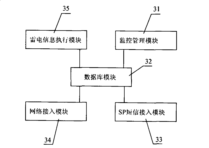
[0064] Embodiment 2, a method for lightning isolation, which utilizes the lightning isolation device shown in Embodiment 1, when actually used (such as Figure 4 As shown), each site is equipped with a monitoring terminal assembly 1 and a disconnector 2; each site is specifically set as follows: one end of the contact of the disconnector 2 is connected to the external mains power supply line 400, and the other end is connected to the base station / direct Put station 100, the drive coil of isolating switch 2 is connected with the contact of intermediate relay 111. The lightning information execution module 35 in the lightning monitoring center platform 3 is connected to the lightning warning system 200 of the Meteorological Bureau through a dedicated line or an E1 transmission network. The monitoring management module 31 is connected with the information input and display device 300 . The specific work can be divided into the following situations:

[0065] Situation 1. Accordi...


PUM


Abstract

The invention discloses a lightning isolation device, which comprises a lightning monitoring center platform (3), at least one monitoring terminal component (1) and an isolating switch (2) corresponding to the monitoring terminal component (1). One end of each monitoring terminal component (1) is connected with the isolating switch (2), and the other end of the monitoring terminal component is connected with the lightning monitoring center platform (3). Simultaneously, the invention also discloses a lightning isolation method using the lightning isolation device. The method and the isolation device can previously cut off the connection between a power supply circuit and electric equipment immediately before lightening occurrence in the location so as to effectively reduce the fault rate of the electric equipment such as a base station or a repeater and the like during lightning strike.

Description

technical field [0001] The invention relates to a lightning isolation method and a used lightning isolation device. Background technique [0002] Every year, a large number of mobile communication base stations and repeaters are struck by lightning, most of which are lightning-induced strong surge currents that are introduced into base stations or repeaters and other equipment through power supply lines, causing equipment damage. Although there are various protection switches and grounding measures, they are basically passive lightning protection measures, which only work when they are struck by lightning. Since it takes time for these measures to work, many devices are still damaged by lightning every year. For this reason, mobile communication operators urgently hope to have a kind of lightning isolation method and used isolation device that actively disconnect the electrical equipment from the power supply line before the lightning comes. Contents of the invention [0...

Claims


Application Information

Patent Timeline
Patent Type & Authority Patents(China)
IPC IPC(8): H02H9/02H04W24/00
Inventor 张科任胡镇毛松苗
Owner HANGZHOU WANGCE COMM TECH
Why Eureka
Try Eureka