Determining method of launch power, base station and terminal thereof
A technology of transmitting power and determining method, applied in the field of communication, can solve problems such as affecting system performance, inflexible control method of transmitting power, etc., to achieve the effect of improving system performance and flexible control
- Summary
- Abstract
- Description
- Claims
- Application Information
AI Technical Summary
Problems solved by technology
Method used
Image
Examples
Embodiment 1
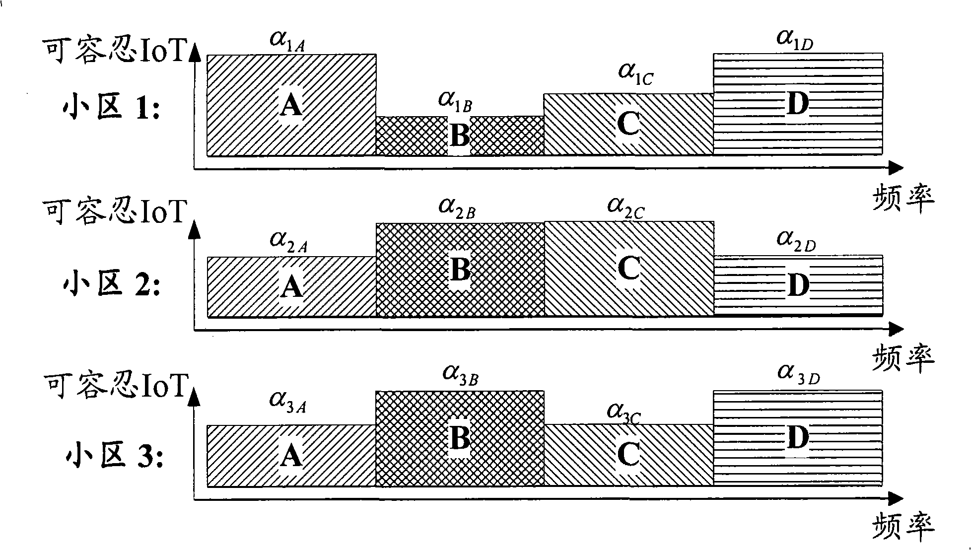
[0062] This embodiment describes that different compensation factors are used in different frequency bands according to IoT.
[0063] figure 2 It is a schematic diagram of a method for determining transmit power according to the tolerable IoT of different frequency sets according to Embodiment 1 of the present invention. Such as figure 2 As shown, each base station sets the tolerable IoT corresponding to different frequency sets (here four frequency sets A, B, C, and D are taken as examples) according to the received IoT indications from neighboring base stations. A set of relatively high IoT frequencies can be tolerated, which means that the inter-cell interference suffered by adjacent cells on this frequency set is very small. Therefore, higher power can be used for transmission, and the compensation factor set for this frequency set is correspondingly larger. IoT sets a smaller compensation factor for lower frequency sets. exist figure 2 in, α 1A 、α 1B 、α 1C and a...
Embodiment 2
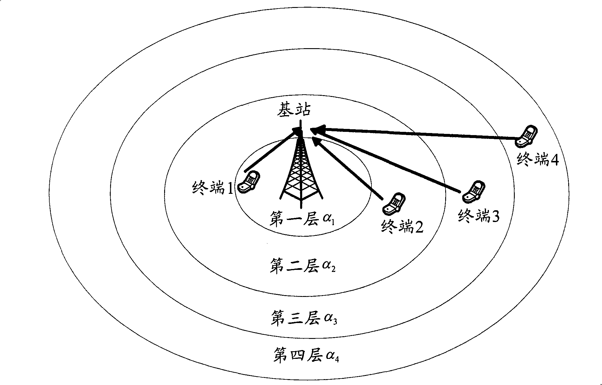
[0066] This embodiment describes that different path loss compensation factors are allocated according to the geographical environment.
[0067] image 3 It is a schematic diagram of a method for determining transmit power according to different geographical environments of a terminal according to Embodiment 2 of the present invention. Such as image 3 As shown, the coverage area of the base station (the base station here also refers to a cell) is divided into multiple layers. Here, the fourth layer is taken as an example. Terminals 1, 2, 3, and 4 are located on the first, second, third, and fourth floors of the base station, respectively. . When FFR is not used, all terminals in the base station can use any frequency band of the system bandwidth. At this time, different path loss compensation factors are set according to the degree of interference caused by terminals in each layer of the base station to adjacent cells, and the path loss compensation factors from the firs...
Embodiment 3
[0070] This embodiment describes that different path loss compensation factors are allocated according to whether the terminal is attached to the relay.
[0071] Figure 4 It is a schematic diagram of a method for determining transmit power when a relay exists in a cell according to Embodiment 3 of the present invention. Such as Figure 4 As shown, terminal 1 and terminal 2 are terminals attached to relay 1, and terminal 3 is a terminal attached to relay 2. Terminal 4 and Terminal 5 are not attached to any relay terminal. A terminal attached to a relay needs to establish a connection with the base station through its attached relay, while a terminal not attached to the relay directly establishes a connection with the base station. The terminals attached to the relay (terminal 1, 2 and 3) are very close to the relay (relay 1 and 2), where terminal 1 and 2 are very close to relay 1, and terminal 3 is very close to relay 2, therefore, The uplink communication with the relay c...
PUM
 Abstract
Description
Claims
Application Information
 - R&D Engineer
- R&D Manager
- IP Professional
- Industry Leading Data Capabilities
- Powerful AI technology
- Patent DNA Extraction
Browse by: Latest US Patents, China's latest patents, Technical Efficacy Thesaurus, Application Domain, Technology Topic, Popular Technical Reports.
© 2024 PatSnap. All rights reserved.Legal|Privacy policy|Modern Slavery Act Transparency Statement|Sitemap|About US| Contact US: help@patsnap.com


