
Optical lens group

An optical lens and lens technology, which is applied in the field of optical lens sets, can solve the problems of the second lens 26 being skewed, the supporting position is not fixed, and the mirror spacing is out of specification, so as to achieve the effects of reducing the impact, not easy to skew, and easy to assemble

Inactive Publication Date: 2009-09-09
HONG FU JIN PRECISION IND (SHENZHEN) CO LTD +1
View PDF0 Cites 6 Cited by
  • Summary
  • Abstract
  • Description
  • Claims
  • Application Information

AI Technical Summary

Problems solved by technology

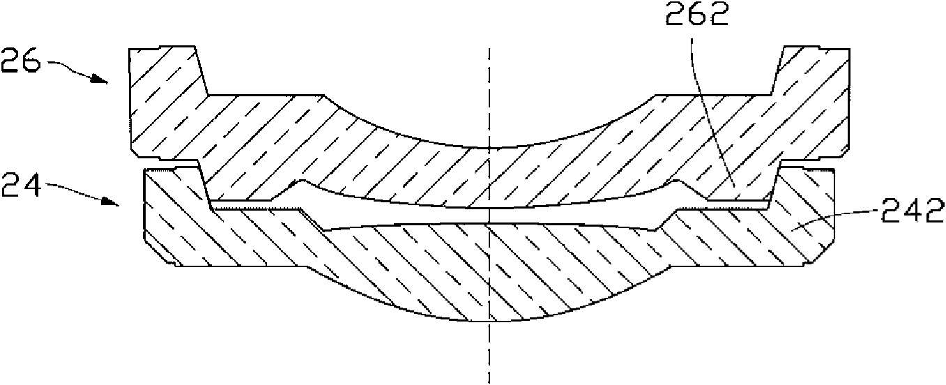
However, this setting requires relatively strict manufacturing tolerances for the slopes of the step 242 and the boss 262. Once the matching tolerances between the slopes are different, the interlocking depth of the second lens 26 into the first lens 24 will also be different, resulting in a gap between the mirrors. If it is out of specification, and the supporting position is not fixed, it is also easy to cause the second lens 26 to be skewed during assembly, so that the optical axes of the first lens 24 and the second lens 26 are not on a straight line, resulting in a deviation, which in turn affects the optical lens group. image quality

Method used


Image

  • Optical lens group
  • Optical lens group
  • Optical lens group

Examples


Embodiment Construction

[0011] The embodiments of the present invention will be further described in detail below in conjunction with the accompanying drawings.

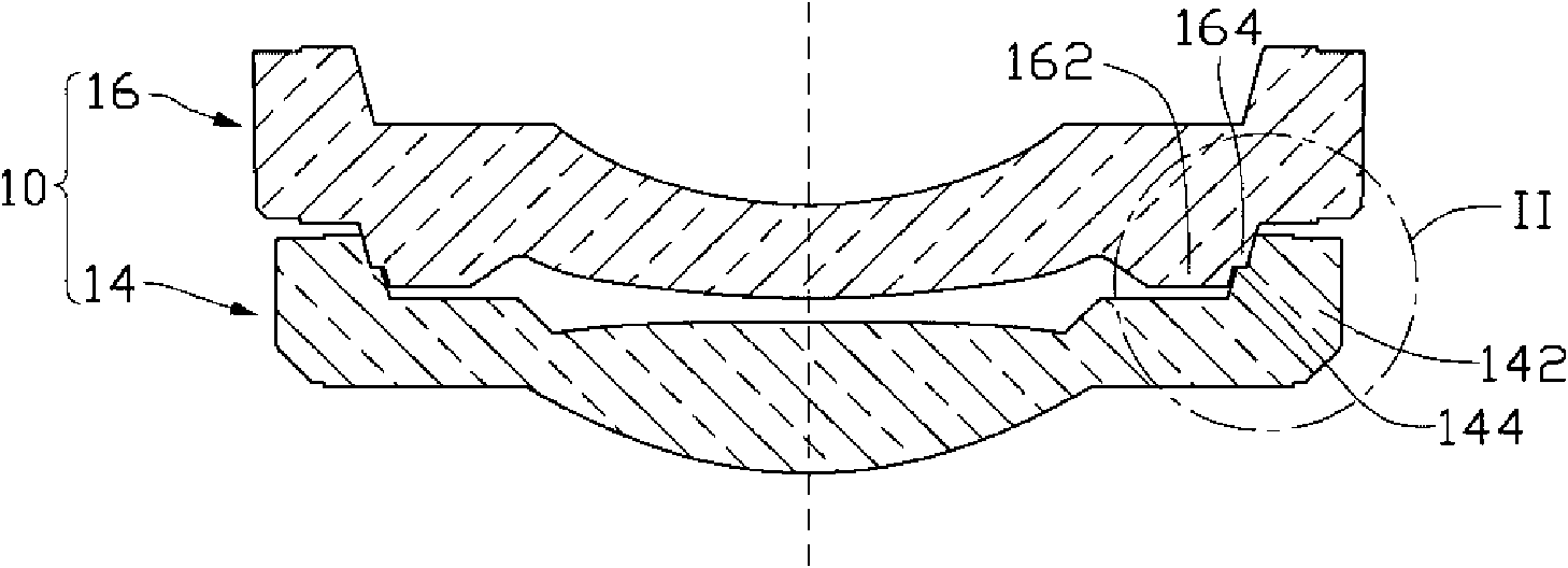
[0012] see figure 1 , which is an optical lens set 10 provided by the embodiment of the present invention, which includes a first lens 14 and a second lens 16 .

[0013] The first lens 14 includes an optical part at the center of the lens and a fixing part at the periphery of the lens for fixing the lens. The optical part is used to achieve a certain optical effect during the imaging process, while the fixing part is only used to fix the lens and does not participate in the imaging. A protruding step 142 is disposed on the periphery of the first lens 14 . The steps are distributed in a ring shape with the lens center of the first lens 14 as the center.

[0014] Similarly, the second lens 16 also includes an optical portion located at the center of the lens and a fixing portion located at the periphery of the lens for fixing the lens. T...


PUM


Abstract

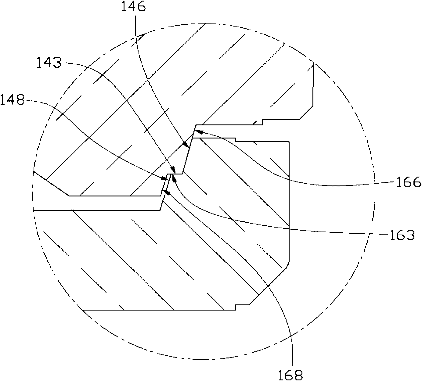
The invention relates to an optical lens group which comprises a first lens and a second lens, wherein the circumference of the first lens is provided with a protrudent step, the circumference of the second lens is provided with a boss matched with the step of the first lens, the contact surfaces of the step and the boss are both inclined surfaces with the same inclination angle, the step and the boss are mutually in the immovable fit to fix the second lens and the first lens, and the section of the inclined surface of the step is provided with a sub-step so that the section of the inclined surface of the step is divided into a first inclined surface and a second inclined surface, the section of the inclined surface of the boss is provided with a sub-boss so that the section of the inclined surface of the boss is divided into a third inclined surface and a fourth inclined surface, the first inclined surface is in matched contact with the third surface so that the sub-step and the sub-boss mutually abut and fix, and a clearance is left between the second inclined surface and the fourth inclined surface.

Description

technical field [0001] The invention relates to an optical lens group, in particular to an optical lens group used in lens modules of electronic products such as mobile phones and digital cameras. Background technique [0002] In recent years, with the development of multimedia technology, the scope of application of lens modules has become wider and wider, such as being applied to electronic products such as digital cameras, video cameras, and mobile phones with camera functions. [0003] While people are pursuing the miniaturization of digital cameras, video cameras and mobile phones with camera functions, they also put forward higher requirements for the image quality of the objects they shoot, that is, they hope that the images of the objects they shoot are clear. The imaging quality of an object largely depends on whether the optical axes of the lenses in the lens module are aligned during the assembly process. In the paper Zoom LensCalibration For Wind Tunnel Measurem...

Claims


Application Information

Patent Timeline
Patent Type & Authority Applications(China)
IPC IPC(8): G02B7/02
CPCG02B13/005
Inventor 黄建峰
Owner HONG FU JIN PRECISION IND (SHENZHEN) CO LTD
Learn More