Automatic alarm of oil filter
What is Al technical title?
Al technical title is built by PatSnap Al team. It summarizes the technical point description of the patent document.
An automatic alarm device and oil filter technology, applied in the installation/connection of pressure lubricating safety devices, lubricant purification devices, filtration and separation, etc., can solve the problems of ignoring the consequences of filter elements, clogging, etc., and achieve easy promotion, Flexible layout and good adaptability
Inactive Publication Date: 2012-04-25
ZHEJIANG UNIV
View PDF0 Cites 0 Cited by
Summary
Abstract
Description
Claims
Application Information
AI Technical Summary
This helps you quickly interpret patents by identifying the three key elements:
Problems solved by technology
Method used
Benefits of technology
Problems solved by technology
[0006] However, the current oil filter alarm device only has the function of clogging alarm, and ignores the breakdown of the filter element and its consequences
Method used
Image
Click on the blue label to locate the original text in one second.
Reading with bidirectional positioning of images and text.
Examples
Embodiment Construction
[0030] Below in conjunction with accompanying drawing, the present invention is described in further detail:
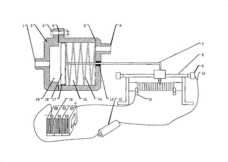
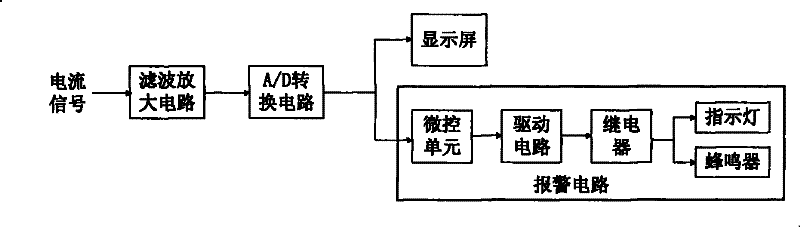
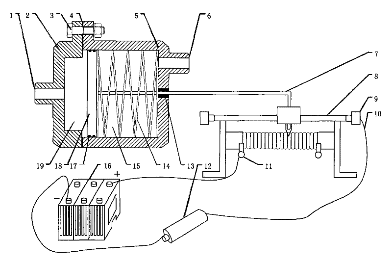
[0031] like figure 1 , figure 2 As shown, the oil filter in this embodiment includes two parts: a signal generating unit and a signal processing circuit. Among them, the former includes four parts: engine oil chamber housing, potentiometer 8, battery 16, and protection resistor 12, while the latter includes four parts: filter amplifier circuit, A / D conversion circuit, display screen, and alarm circuit. .
[0032] like figure 1 As shown, the oil chamber housing includes two housings, the pre-filter oil chamber shell 2 and the filter oil chamber shell 5, both of which have an oil inlet 1, 6 respectively. There is a sealing ring 4 between the housings 2 and 5, which are connected together by three bolt fasteners 3 evenly distributed around the circumference, forming a cavity inside. There is a spring 14 and a piston 18 inside the engine oil chamber housing. The t...
PUM
Abstract
The invention relates to an automatic alarm and aims at providing an automatic alarm of an oil filter for a gas engine. The automatic alarm comprises an oil cavity shell formed by butting a before-filThe invention relates to an automatic alarm and aims at providing an automatic alarm of an oil filter for a gas engine. The automatic alarm comprises an oil cavity shell formed by butting a before-filtering oil cavity casing and an after-filtering oil cavity casing, wherein the oil cavity shell is internally provided with a spring and a piston, two ends of the spring are respectively fixed on thetering oil cavity casing and an after-filtering oil cavity casing, wherein the oil cavity shell is internally provided with a spring and a piston, two ends of the spring are respectively fixed on theinner wall of an after-filtering oil cavity and the piston, and the piston divides the cavity formed inside the two casings into two cavities which are not communicated with each other; the piston isinner wall of an after-filtering oil cavity and the piston, and the piston divides the cavity formed inside the two casings into two cavities which are not communicated with each other; the piston isprovided with a sliding rod at one side of the spring, one end of the sliding rod is fixedly connected with the piston, and the other end passes through the wall of the after-filtering oil cavity casiprovided with a sliding rod at one side of the spring, one end of the sliding rod is fixedly connected with the piston, and the other end passes through the wall of the after-filtering oil cavity casing and is connected with a sliding part on a potentiometer; the potentiometer is connected with the battery by a lead to form a loop, and the loop is sequentially connected with a filtering amplificatng and is connected with a sliding part on a potentiometer; the potentiometer is connected with the battery by a lead to form a loop, and the loop is sequentially connected with a filtering amplification circuit, an A / D switching circuit, and an alarm circuit. The automatic alarm can continuously display the working status of the oil filter, and has perfect function, reliable property, good adaptaion circuit, an A / D switching circuit, and an alarm circuit. The automatic alarm can continuously display the working status of the oil filter, and has perfect function, reliable property, good adaptability, simple structure, small volume, flexible arrangement, low fabrication cost and easy popularization.bility, simple structure, small volume, flexible arrangement, low fabrication cost and easy popularization.
Description
technical field [0001] The invention relates to an automatic alarm device, in particular to an automatic alarm device for an oil filter used in an internal combustion engine. technical background [0002] The oil filter is responsible for filtering the medium in the engine lubrication system, ensuring the normal operation of the engine, and improving efficiency and extending the operating life. The oil filter is an important component of the lubrication system. The function of the lubrication system is to continuously provide clean oil to the friction surfaces of the relative moving parts of the engine, and form an oil film between the friction surfaces to achieve liquid friction, so as to achieve the purpose of durability and reliability of the engine. The lubrication system plays an important role in ensuring the normal operation of the engine. The engine oil flows back to the oil pan after passing through each friction surface, which will contain various metal wear deb...
Claims
Application Information
Patent Timeline
Application Date:The date an application was filed.
Publication Date:The date a patent or application was officially published.
First Publication Date:The earliest publication date of a patent with the same application number.
Issue Date:Publication date of the patent grant document.
PCT Entry Date:The Entry date of PCT National Phase.
Estimated Expiry Date:The statutory expiry date of a patent right according to the Patent Law, and it is the longest term of protection that the patent right can achieve without the termination of the patent right due to other reasons(Term extension factor has been taken into account ).
Invalid Date:Actual expiry date is based on effective date or publication date of legal transaction data of invalid patent.
