
Automatic monitoring apparatus and method for layered vertical sedimentation and lateral displacement of roadbed

A technology of vertical settlement and lateral displacement, applied in the field of optical measurement, which can solve problems such as shallow measurement depth, low measurement accuracy, and inability to automatically monitor, and achieve the effect of improving measurement efficiency and accuracy

Inactive Publication Date: 2009-07-08
BEIJING JIAOTONG UNIV
View PDF0 Cites 56 Cited by
  • Summary
  • Abstract
  • Description
  • Claims
  • Application Information

AI Technical Summary

Problems solved by technology

[0004] The purpose of the present invention is to provide a device that utilizes laser measurement technology to automatically monitor the vertical settlement and lateral displacement of subgrade layers at the same time and an automatic monitoring method based on the device, so as to solve the problem of low measurement accuracy and poor measurement accuracy of the currently used subgrade settlement and deformation detection methods. Problems such as shallow depth, high requirements for the measurement environment, and inability to monitor remotely and automatically

Method used


Image

  • Automatic monitoring apparatus and method for layered vertical sedimentation and lateral displacement of roadbed
  • Automatic monitoring apparatus and method for layered vertical sedimentation and lateral displacement of roadbed
  • Automatic monitoring apparatus and method for layered vertical sedimentation and lateral displacement of roadbed

Examples


Embodiment Construction

[0038] The preferred embodiments will be described in detail below in conjunction with the accompanying drawings. It should be emphasized that the following description is only exemplary and not intended to limit the scope of the invention and its application.

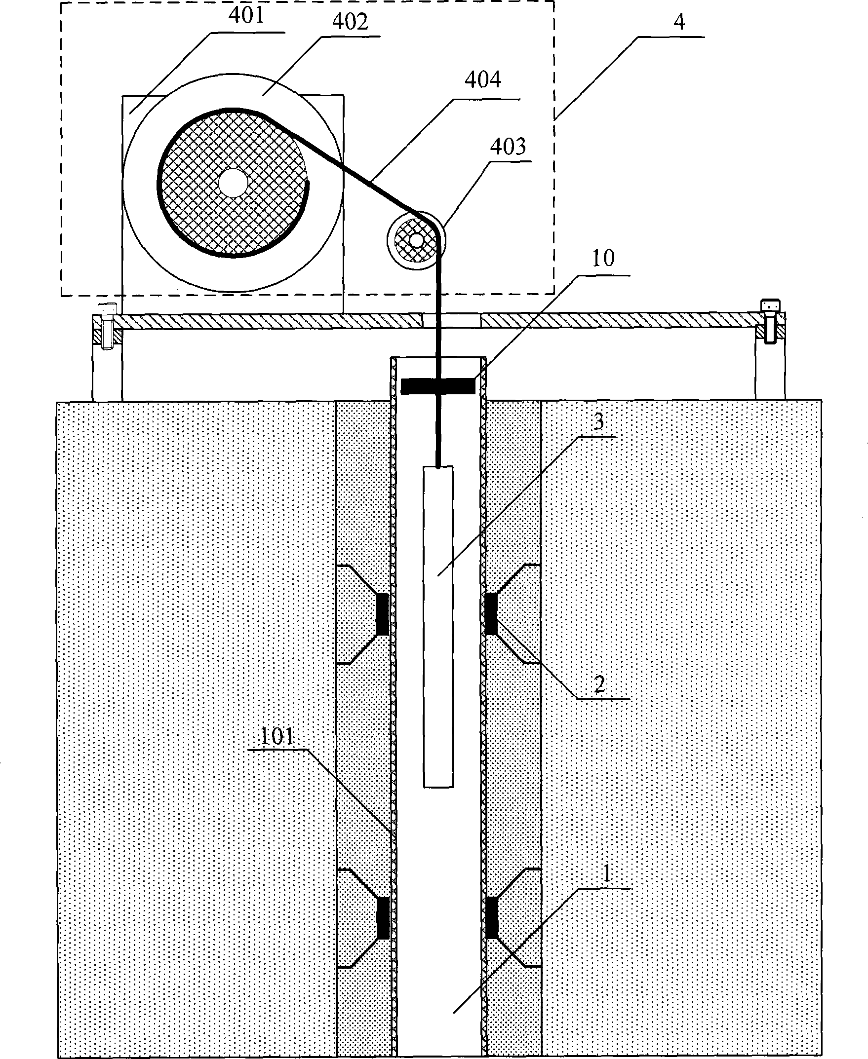
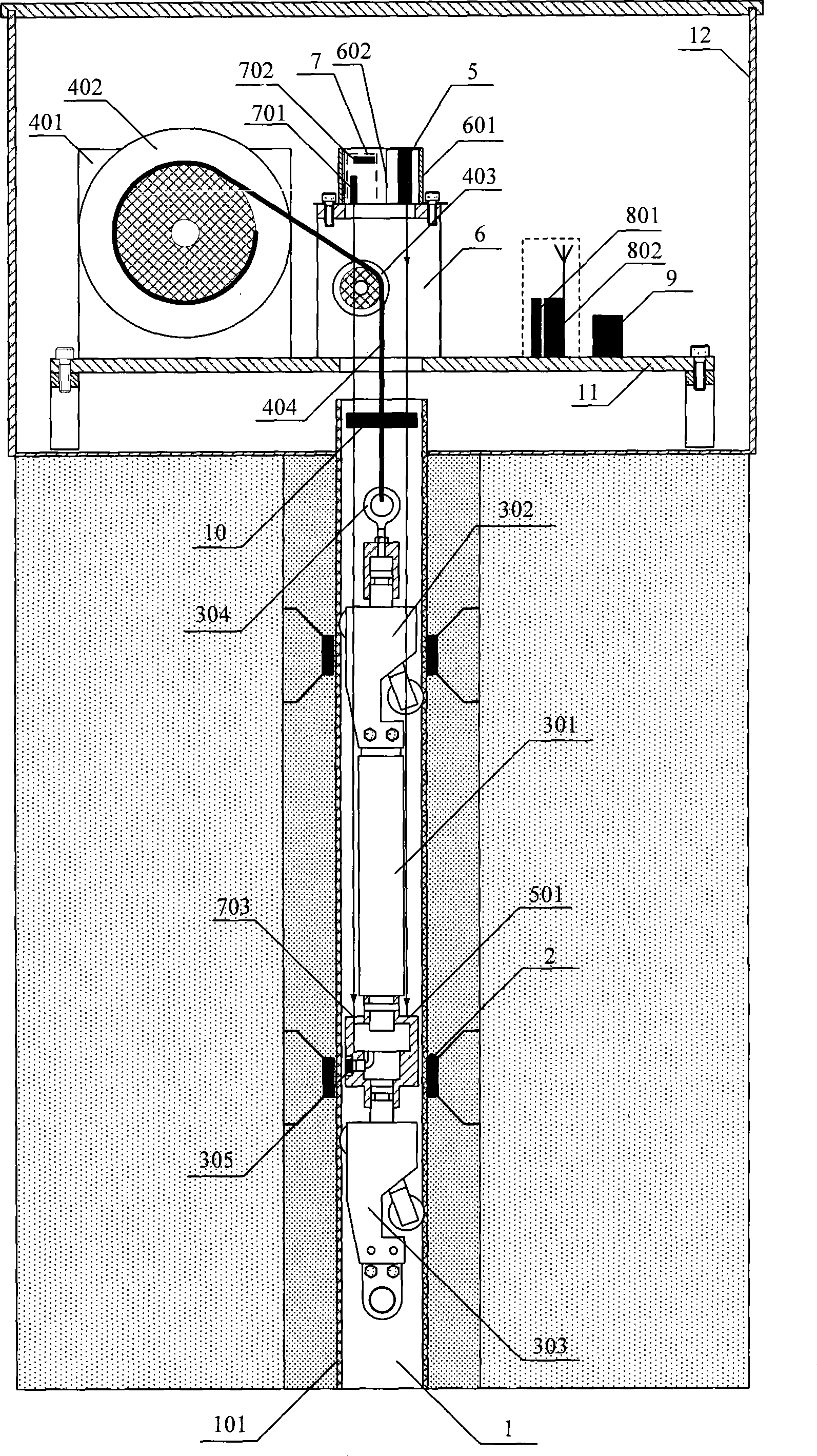
[0039] figure 1 is the schematic diagram of the measurement positioning unit. figure 1Among them, the measurement and positioning unit is composed of an inclinometer tube 1, a magnetic ring 2, a measuring rod 3, a lifting device 4, and a limit switch 10. The inclinometer tube 1 and the magnetic ring 2 are buried in the subgrade to be tested by drilling in advance, and the magnetic ring 2 will be buried in various observation points at different depths under the subgrade, and the holes will be sealed with expansive soil, and the magnetic ring will settle synchronously with the formation.

[0040] The lifting device 4 is made up of a motor 401 , a reel 402 , a pulley 403 , a cable or a safety rope 404 . The cable is c...


PUM


Abstract

The invention discloses a road foundation layered vertical settlement and transversal displacement automatic monitoring device and a monitoring method thereof in the technical field of optical measurement. The invention adopts a technical proposal that the automatic monitoring device comprises a measuring and positioning unit, a laser displacement sensing unit, a laser angle sensing unit, a measuring signal control unit, a measuring data transmission unit, a central processing unit and a power module; and the automatic monitoring method comprises: firstly, assembling various devices; secondly, starting a pulling device, stopping the device when a positioning sensor arrives at a position of a magnetic ring, measuring displacement data and angle data, and transmitting the data to the central processing unit for storage; thirdly, restarting the pulling device, and repeatedly measuring and saving the data until a measuring tube contacts a limit switch; and processing all the data of the central processing unit, and obtaining road foundation vertical settlement and transversal displacement parameters. The automatic monitoring device and the automatic monitoring method apply laser measurement technology, improve the measurement precision and the measurement depth, and simultaneously realize remote automatic monitoring.

Description

technical field [0001] The invention belongs to the technical field of optical measurement, and in particular relates to an automatic monitoring device and a monitoring method for vertical settlement and lateral displacement of subgrade layers. Background technique [0002] High-speed driving is an important symbol of railway modernization, and the dynamic effect of trains on high-speed railways is much greater than that of ordinary railways, which poses new challenges to the design, construction, and testing of traditional railways in my country, especially for the control of subgrade settlement and deformation. Therefore, it is necessary to carry out long-term automatic monitoring of the settlement and deformation of the subgrade, timely maintain the subgrade that does not meet the requirements, and adopt different construction methods to control its settlement and deformation. Therefore, research on methods that can quickly and accurately monitor subgrade settlement and de...

Claims


Application Information

Patent Timeline
IPC IPC(8): E02D33/00
Inventor 冯其波张斌崔建英陈士谦颊东耀高瞻邵双远
Owner BEIJING JIAOTONG UNIV
Learn More