Calibration apparatus for six-dimension heavy force sensor
What is Al technical title?
Al technical title is built by PatSnap Al team. It summarizes the technical point description of the patent document.
A technology of calibration device and force sensor, applied in the direction of measurement device, instrument, force/torque/work measuring instrument calibration/test, etc., to achieve the effect of high precision and compact structure
Active Publication Date: 2010-07-07
DALIAN UNIV OF TECH
View PDF0 Cites 3 Cited by
Summary
Abstract
Description
Claims
Application Information
AI Technical Summary
This helps you quickly interpret patents by identifying the three key elements:
Problems solved by technology
Method used
Benefits of technology
Problems solved by technology
The weight-type loading method can realize the individual calibration of each force, but due to the weight limit of the weight, even if the lever principle is used to lengthen the force arm, it is impossible to calibrate the large value range, and its structure is not compact, and the loading accuracy is not high.
The gantry-type calibration device can also perform comprehensive calibration of the six-dimensional force of the sensor. It has good operability, compact structure, and good rigidity, but it is difficult to calibrate large-scale sensors, and the upper limit of the force value cannot be very high It can meet the working requirements of large force sensors in giant heavy-duty equipment
Giant heavy-duty operating equipment has the characteristics of large inertia, multiple degrees of freedom, and variable stiffness. Vigorous force sensor is used for static calibration, so the traditional calibration device mentioned above cannot meet the calibration requirements of six-dimensional force sensor
Method used
Image
Click on the blue label to locate the original text in one second.
Reading with bidirectional positioning of images and text.
Examples
Embodiment Construction
[0015] The concrete implementation of the present invention is described in detail in conjunction with accompanying drawing and technical scheme:
[0016] 1) The installation of the large force loading mechanism and the calibrated mechanism
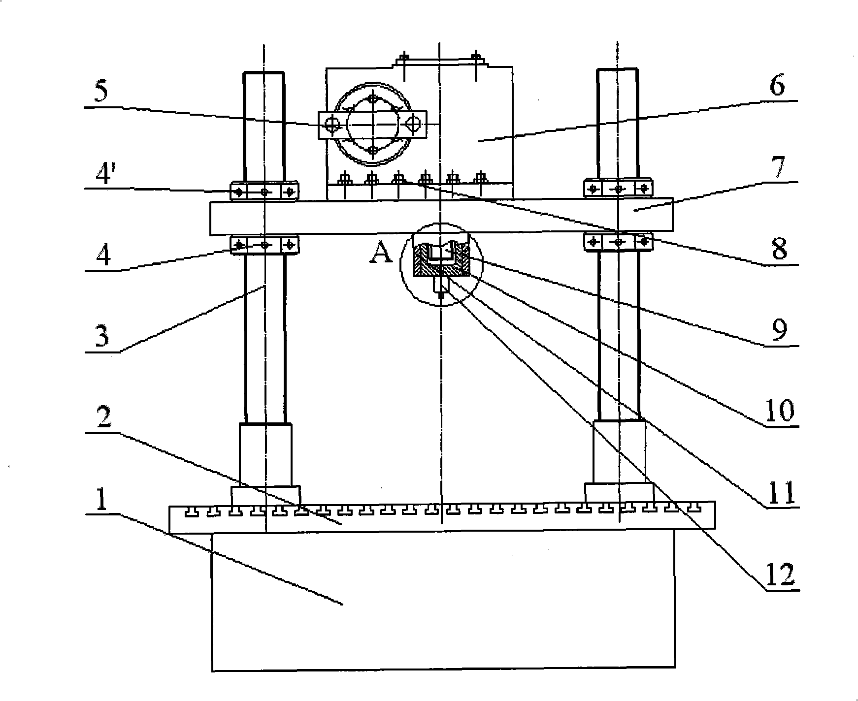
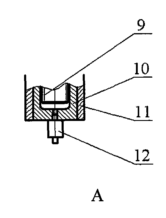
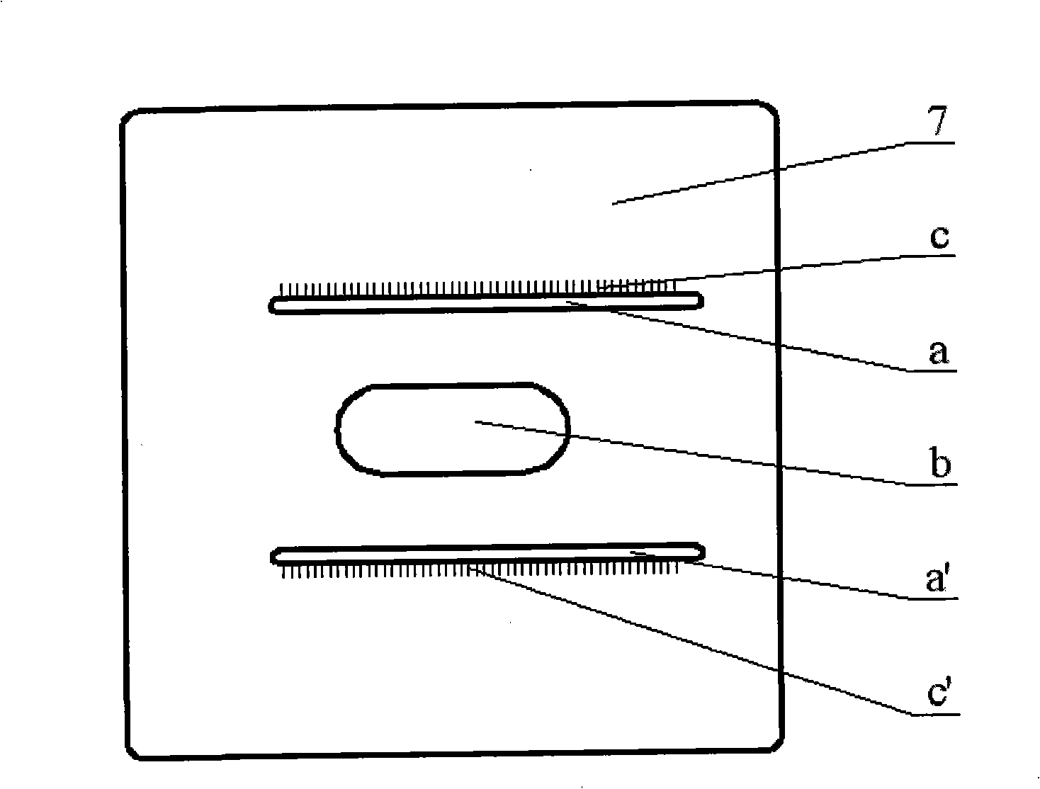
[0017] Install the upper support plate 7 on the four columns 3, and fix it with eight up and down lifting nuts 4, 4', the high force value loading mechanism 6 is placed on the upper surface of the upper support plate 7, and the large force value loading mechanism 6 outputs The end passes through the central long hole b of the upper supporting plate 7, the output end of the high force loading mechanism 7 can translate left and right in the central long hole b, and is adjusted by the scale d on the high force loading mechanism 6 and the scale c of the upper supporting plate 7 The left and right positions of the great value loading mechanism 6 make the axis of the standard unidirectional force sensor 12 connected to the output end of the gre...
PUM
Abstract
The invention provides a calibration device of a six-dimensional heavy force sensor, and belongs to the field of sensors as well as the measurement and the control thereof. By adopting a single force source, the calibration device is capable of calibrating the six-dimensional force of a force sensor. The calibration device comprises a base, a calibration workbench, an upright post, a lifting nut,a handle, a large force value loading mechanism adopting a worm wheel and a worm for transmission, an upper support tablet, a lead screw, a nut, a sleeve, a standard uni-directional force sensor, a ranging rod, a bolt, a connection block, an L-shaped plate, a sensor to be calibrated, a working shaft, a positioning pin, a base plate, a T-shaped bolt and a signal wire; and a mechanism to be calibrated consists of the ranging rod, the bolt, the connection block, the L-shaped plate, the sensor to be calibrated, the working shaft, the positioning pin and the base plate. The device is capable of loading the six-dimensional heavy force sensor and carrying out systematic calibration. The device has the characteristics of compact structure, simplicity, high rigidity and high precision, and can achieve precise calibration of the six-dimensional heavy force sensor.
Description
technical field [0001] The invention belongs to the field of sensors and measurement and control thereof, in particular to a calibration device for a six-dimensional force sensor of giant heavy-duty operating equipment. Background technique [0002] At present, the calibration devices for sensors at home and abroad are mainly weight-type and gantry-type calibration devices. The weight-type loading method can realize the individual calibration of each force, but due to the weight limit of the weight, even if the lever principle is used to lengthen the force arm, it is impossible to calibrate the large value range, and its structure is not compact, and the loading accuracy is not high. . The gantry-type calibration device can also perform comprehensive calibration of the six-dimensional force of the sensor. It has good operability, compact structure, and good rigidity, but it is difficult to calibrate large-scale sensors, and the upper limit of the force value cannot be very...
Claims
Application Information
Patent Timeline
Application Date:The date an application was filed.
Publication Date:The date a patent or application was officially published.
First Publication Date:The earliest publication date of a patent with the same application number.
Issue Date:Publication date of the patent grant document.
PCT Entry Date:The Entry date of PCT National Phase.
Estimated Expiry Date:The statutory expiry date of a patent right according to the Patent Law, and it is the longest term of protection that the patent right can achieve without the termination of the patent right due to other reasons(Term extension factor has been taken into account ).
Invalid Date:Actual expiry date is based on effective date or publication date of legal transaction data of invalid patent.