Pressure adjusting valve for vehicle fuel line

A fuel pipeline and pressure regulation technology, applied in the field of pressure regulating valves, can solve problems such as inability to accurately adjust fuel pressure

Inactive Publication Date: 2009-06-17
HYUNDAI MOTOR CO LTD
View PDF3 Cites 5 Cited by
  • Summary
  • Abstract
  • Description
  • Claims
  • Application Information

AI Technical Summary

Problems solved by technology

[0004] The valve can only be opened or closed, so it cannot precisely adjust fuel pressure

Method used


Image

  • Pressure adjusting valve for vehicle fuel line
  • Pressure adjusting valve for vehicle fuel line
  • Pressure adjusting valve for vehicle fuel line

Examples


Embodiment Construction

[0015] Next, illustrative embodiments of the present invention will be described in detail with reference to the accompanying drawings.

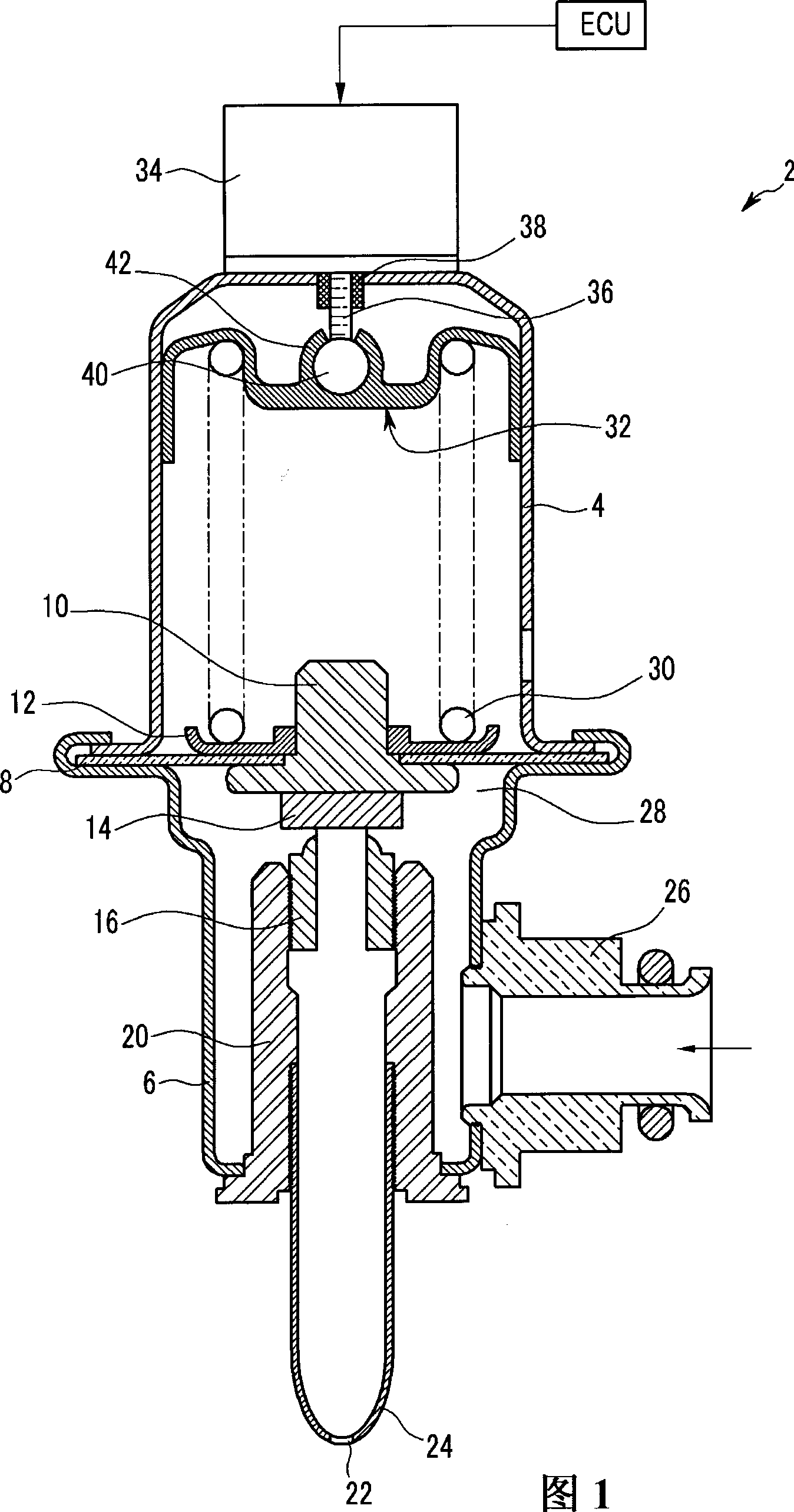
[0016] Referring to FIG. 1 , a pressure regulating valve 2 for a vehicle fuel line (not shown) includes a cylindrical upper case 4 and a cylindrical lower case 6 . A diaphragm 8 is interposed between the upper case 4 and the lower case 6 , and an inner body 10 is disposed inside the diaphragm 8 . The spring seat 12 is arranged on the diaphragm 8 . The valve plate 14 is attached to the bottom of the inner valve body 10 , and the valve plate 14 opens and closes the valve body 16 disposed inside the bush 20 . Fuel nozzles 24 with outlets 22 are disposed below the liner 20 . A fuel inlet 26 is provided on one side of the lower case 6 . Fuel is supplied through a fuel inlet 26 to a hydraulic chamber 28 located below the diaphragm 8 .

[0017] The fuel pressure inside the hydraulic chamber 28 pushes the diaphragm 8 . If the pressure inside th...


PUM


Abstract

A pressure adjusting valve for a vehicle fuel line includes a diaphragm disposed in a housing and dividing the interior of the housing into first and second compartments. A valve plate is provided in the second compartment and attached to the diaphragm. A return unit is provided in the second compartment. An elastic member provides an elastic force to the diaphragm toward the second compartment. An elastic force adjusting unit controls the elastic force of the elastic member.

Description

[0001] Cross References to Related Applications [0001] This application claims priority and benefit from Korean Patent Application No. 10-2007-0131636 filed with the Korean Intellectual Property Office on December 14, 2007, the entire contents of which are hereby incorporated by reference. technical field [0002] The present invention relates to pressure regulating valves for vehicle fuel lines. Background technique [0003] A typical pressure regulator valve includes a spring biased diaphragm located in the fuel hydraulic chamber. If the pressure in the fuel hydraulic chamber overcomes the force of the spring, the diaphragm is pushed open so that fuel is free to leave the valve through the fuel outlet. [0004] The valve can only be opened or closed, so the fuel pressure cannot be precisely adjusted. [0005] The above information disclosed in this Background section is only for enhancement of understanding of the background of the invention and therefore it may contai...

Claims


Application Information

Patent Timeline
Patent Type & Authority Applications(China)
IPC IPC(8): F02M55/02F16K15/02
CPCF02M69/54G05D16/0655G05D16/2086G05D16/024F02M37/00F02M69/00F16K7/17
Inventor 奉夏东金镇镕黄昇焕黄一中申泰烈崔光淳李相旻
Owner HYUNDAI MOTOR CO LTD
Why Eureka
Try Eureka