
Fast transient step load response in a power converter

A power converter and converter technology, which are applied in the output power conversion device, DC power input conversion to DC power output, high-efficiency power electronic conversion, etc., can solve problems such as stability problems

Active Publication Date: 2009-05-20
ASTEC INT LTD
View PDF4 Cites 14 Cited by
  • Summary
  • Abstract
  • Description
  • Claims
  • Application Information

AI Technical Summary

Problems solved by technology

This may create stability issues in some VRMs

Method used


Image

  • Fast transient step load response in a power converter
  • Fast transient step load response in a power converter
  • Fast transient step load response in a power converter

Examples


Embodiment Construction

[0020] Exemplary embodiments will now be described more fully with reference to the accompanying drawings.

[0021] The exemplary embodiments are provided to make the present invention thorough and complete, and to enable those skilled in the art to fully understand the protection scope of the present invention. Numerous specific details are described herein, as examples of specific components, devices and methods, in order to provide a thorough understanding of embodiments of the invention. It will be apparent to those skilled in the art that specific details may be employed, that exemplary embodiments of the invention may be practiced in many different ways and that these details and examples shall not limit the scope of the invention. In some embodiments, well-known processes, well-known device structures, and well-known technologies are not described in detail.

[0022] The terminology used herein is for the purpose of describing particular exemplary embodiments only and ...


PUM


Abstract

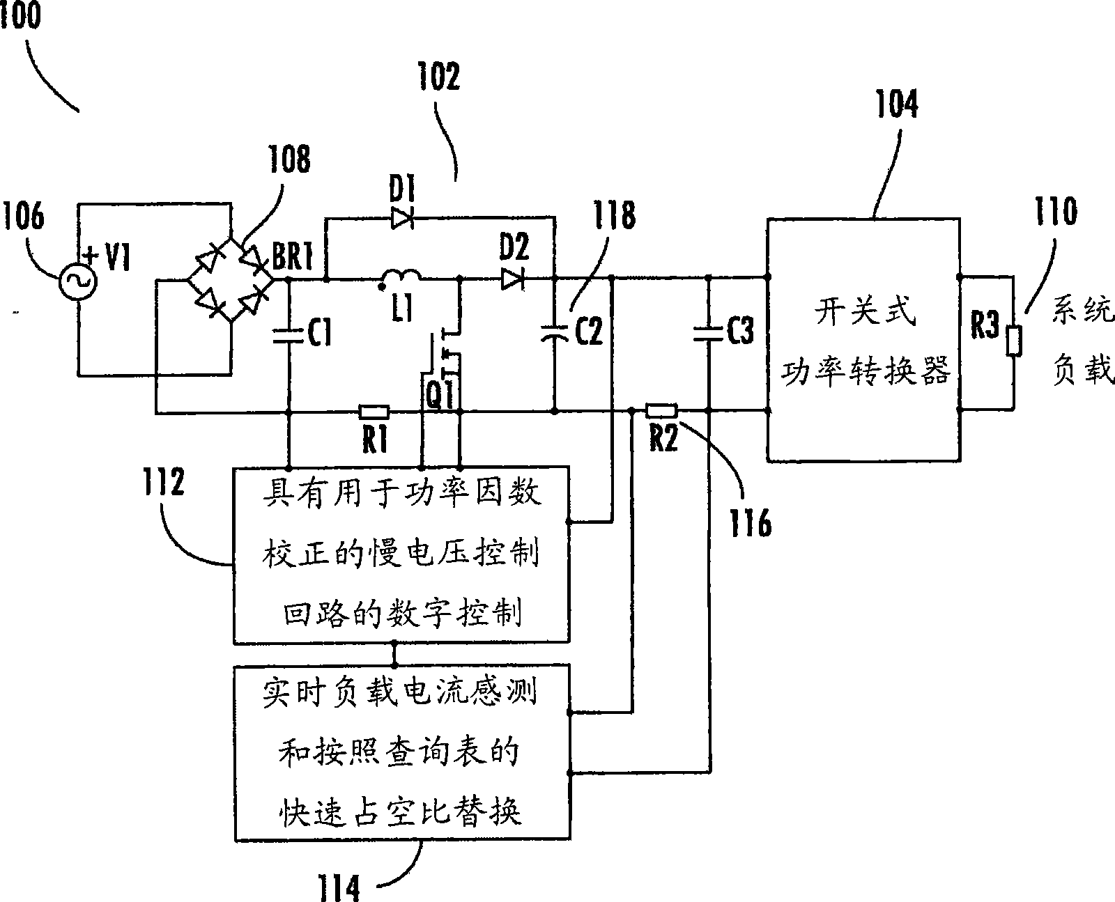
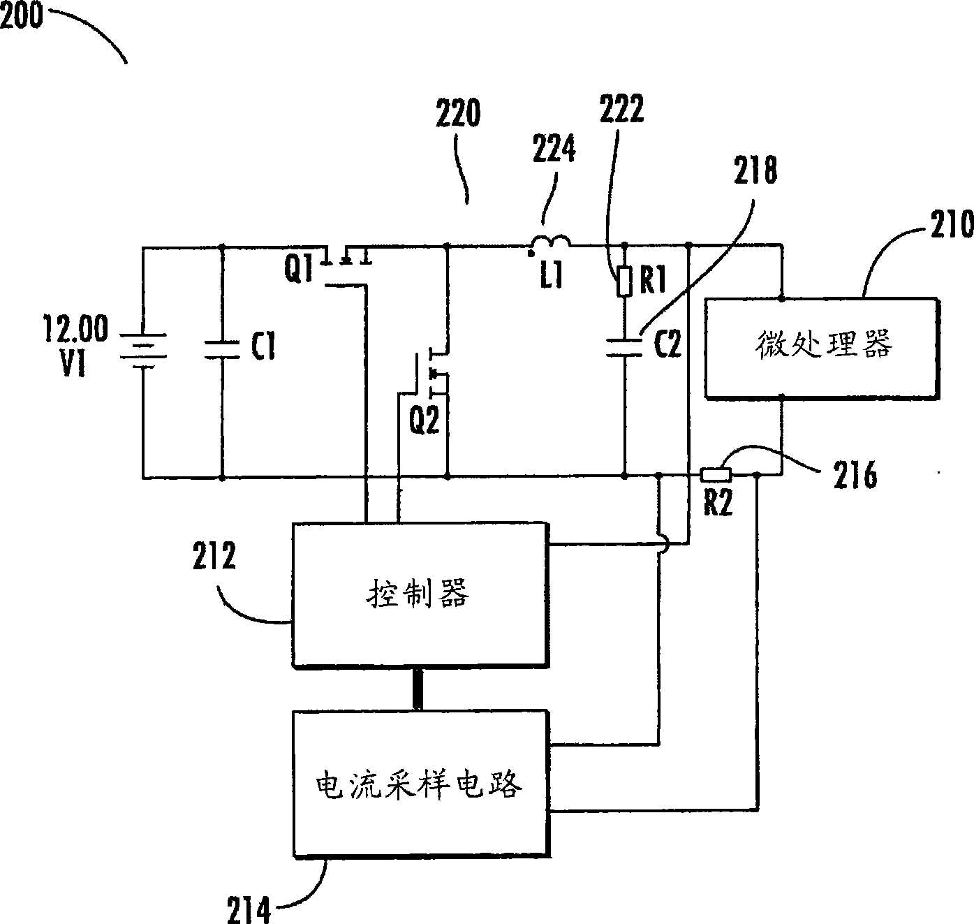
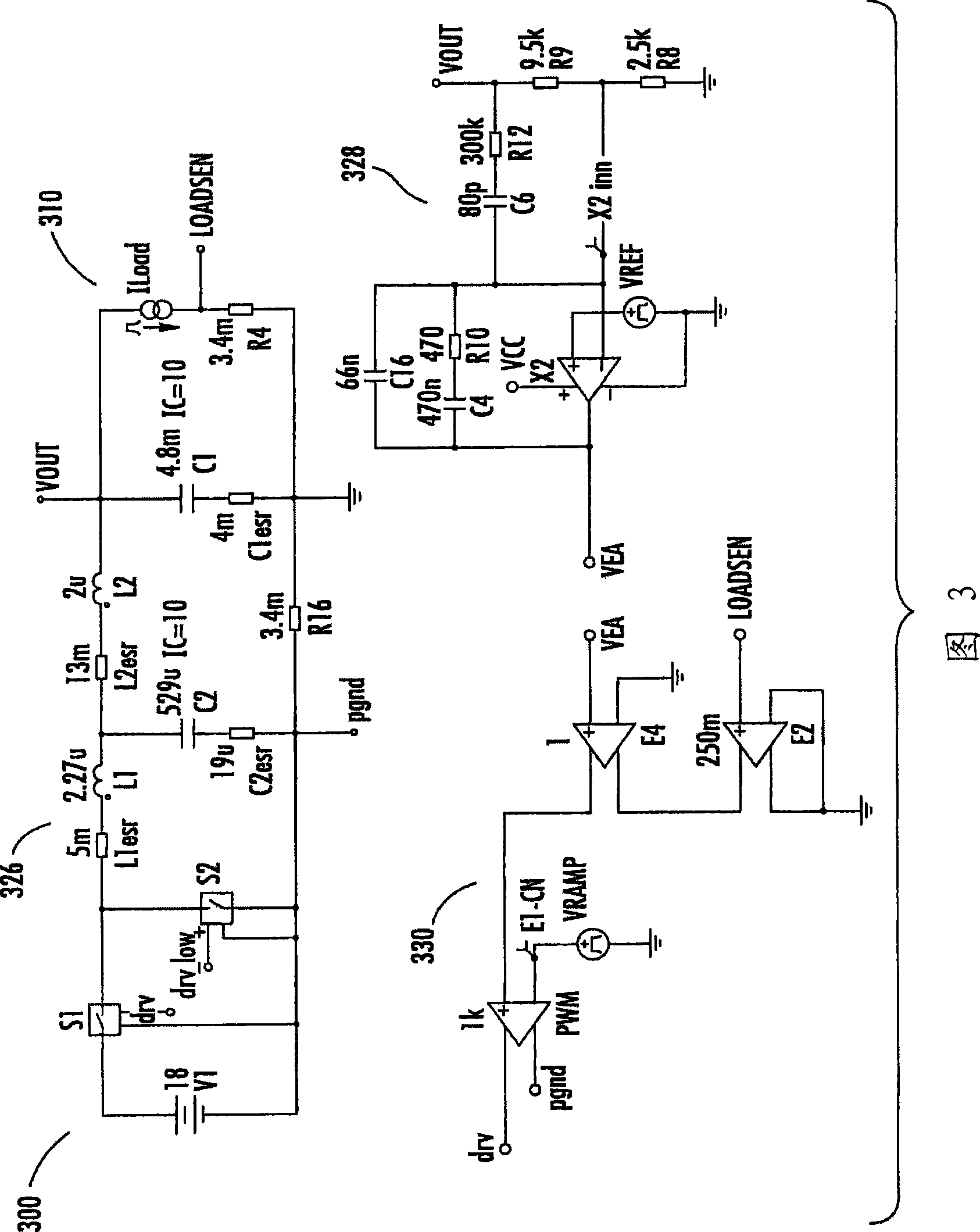
A method of controlling a power converter having at least one switching device for supplying an output voltage and a load current to a load is disclosed. The method includes sensing the output voltage and sensing the load current. The method further includes controlling a duty cycle of the switching device according to the sensed output voltage and a voltage control loop when a rate of change of the load current does not exceed a threshold level. The method also includes adjusting the duty cycle of the switching device set by the voltage control loop when the rate of change of the load current exceeds the threshold level.

Description

[0001] Cross References to Related Applications [0002] This application claims priority to US Provisional Application No. 60 / 997,051 filed September 28,2007. The entire disclosures of the aforementioned applications are incorporated herein by reference. technical field [0003] The present invention relates to power converters. Background technique [0004] This section provides information related to the background of the present invention which may not necessarily constitute prior art. [0005] Many modern electronic systems require high current slew rates. This fast transient step load requires careful design of the power converter's voltage control loop and output filter to keep voltage overshoot and undershoot within required specifications. This often results in reduced output inductors and increased switching frequency. [0006] In a typical PFC boost pre-regulator, large voltage swings in large power supplies are an important factor for sizing the bulk capacito...

Claims


Application Information

Patent Timeline
IPC IPC(8): H02M3/10H02M1/42H02M3/156
CPCY02B70/126Y02B70/10
Inventor 维杰·G·法德克阿兰多·V·阿桑乔恩埃文·M·埃斯皮纳扬西·F·邦凯托
Owner ASTEC INT LTD
Learn More