Electrification demonstration instrument for solar cell
A solar cell and demonstration instrument technology, applied in the field of solar photovoltaic utilization, can solve the problems of not being able to demonstrate the diurnal and annual changes of solar radiation, and the inability to demonstrate changes in the annual power generation of solar cells, etc.
Inactive Publication Date: 2010-11-24
SUN YAT SEN UNIV +1
View PDF0 Cites 0 Cited by
- Summary
- Abstract
- Description
- Claims
- Application Information
AI Technical Summary
Problems solved by technology
Traditional solar cell power generation demonstration devices only demonstrate that solar cells can generate electricity (such as lighting a small light bulb), and cannot demonstrate the daily and annual changes of solar radiation. Of course, they cannot demonstrate the annual power generation of solar cells and their principles.
Method used
View moreImage
Smart ImageViewing Examples
Examples
Embodiment Construction
Login to View More PUM
 Abstract
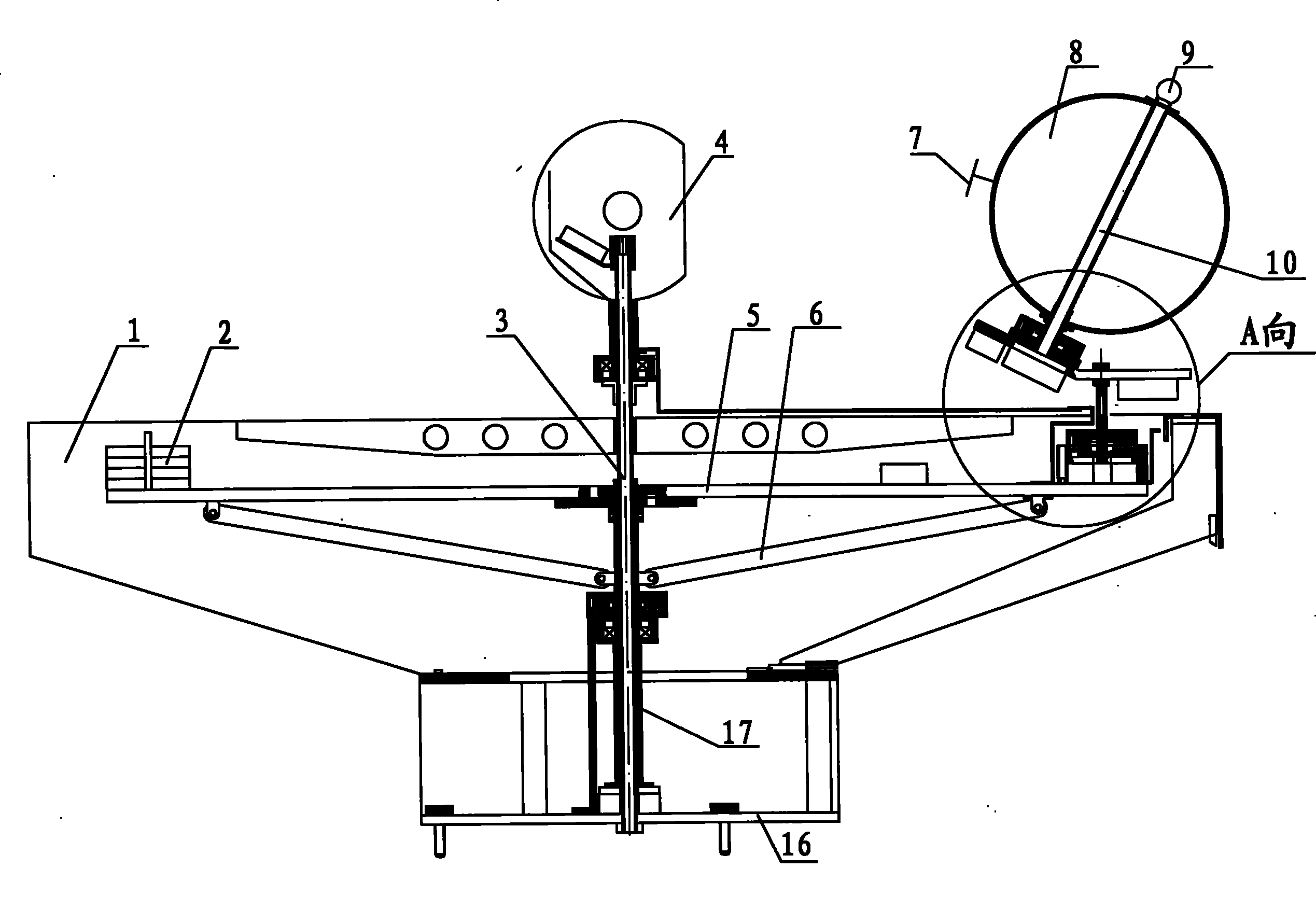
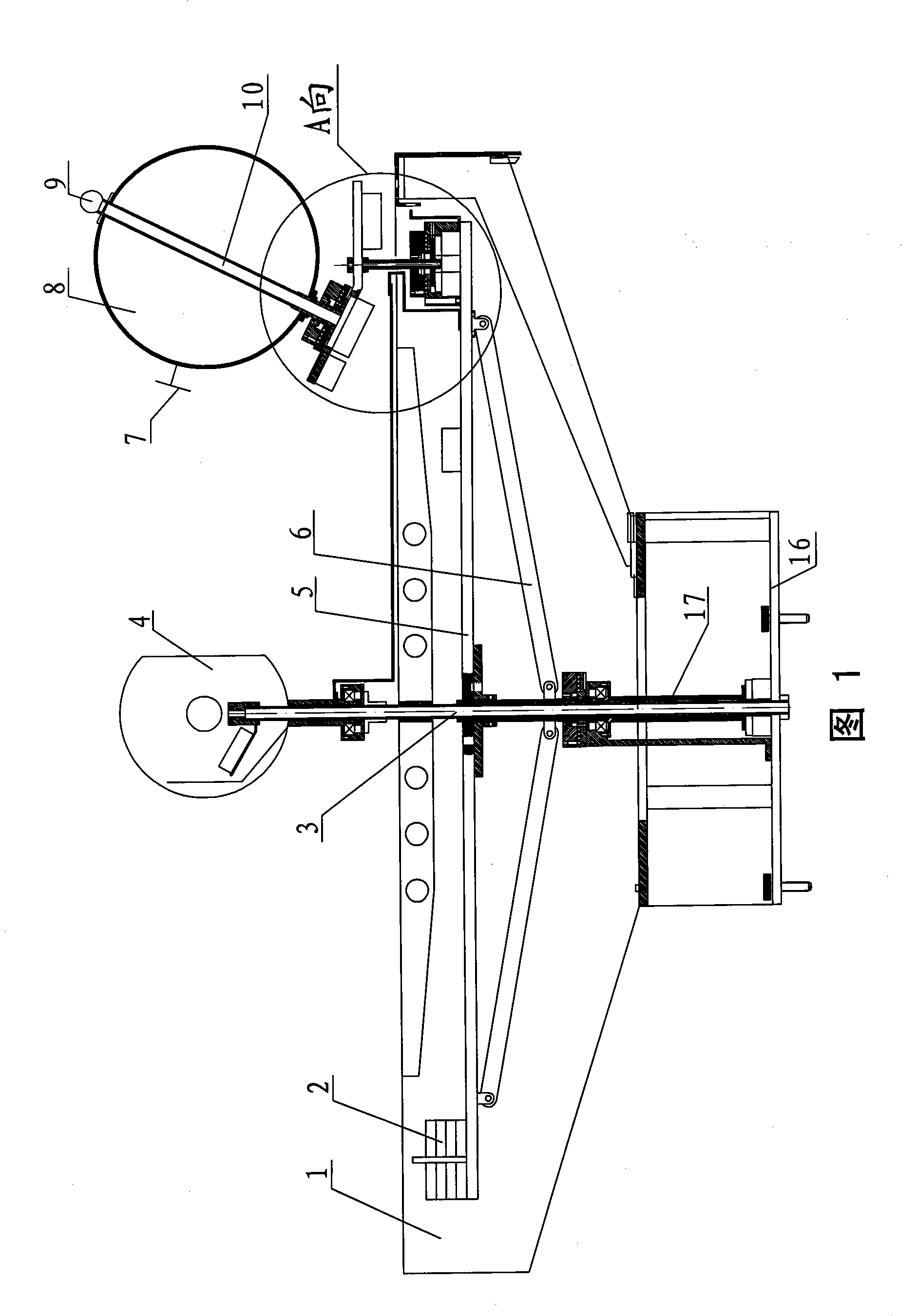
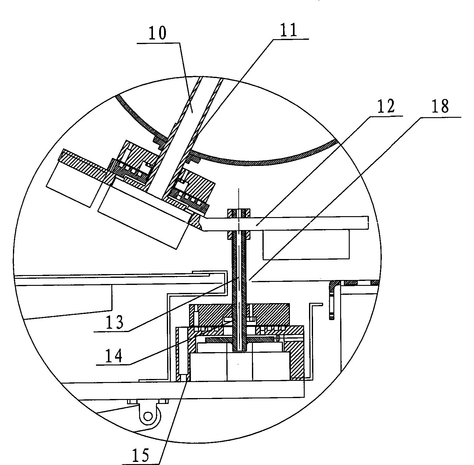
The invention discloses a demonstration apparatus for the power generation of a solar battery. The demonstration apparatus comprises an earth model, a simulated sun, a simulated orbit on which the earth revolves around the sun, a mechanical mechanism and an electrical control mechanism; the earth model is provided with the solar battery and an indicator light of the solar battery; the mechanical mechanism comprises a revolution mechanism, an earth axis mechanism and a rotation mechanism; and the electrical control mechanism controls the motions of the revolution mechanism, the earth axis mechanism and the rotation mechanism by an interface to drive the earth model to revolve around the simulated sun to perform simulated motion on the simulated orbit on which the earth revolves around the sun according to the solar-terrestrial relationship. The demonstration apparatus for the power generation of the solar battery can demonstrate the power generation of the solar battery, and demonstrate the daily change and the annual change of the solar radiation, the annual generating capacity change of the solar battery resulting from the daily change and the annual change as well as the principle thereof; meanwhile, the demonstration apparatus can demonstrate other astronomy-related knowledge.
Description
A solar cell power generation demonstration instrument technical field The invention relates to the field of photovoltaic utilization of solar energy, in particular to a solar cell power generation demonstration instrument. Background technique A solar cell refers to a device that directly converts solar radiation energy into electrical energy. Since the invention of solar cells in 1954, the application of solar cells has entered a period of rapid growth, and the annual growth rate has exceeded 50% in recent years. The index that marks the power generation capacity of solar cells is power generation efficiency. People have developed different materials or processes to produce various types of solar cells, the main purpose of which is to improve the efficiency of power generation, or to improve the efficiency of solar cells to absorb and utilize solar energy. In specific applications, it is necessary to make the sun's rays incident on the solar cell vertically as much as...
Claims
Login to View More Application Information
Patent Timeline
 Patent Type & Authority Patents(China)
IPC IPC(8): G09B23/00G09B27/00
Inventor 邓幼俊王丙祥沈辉
Owner SUN YAT SEN UNIV
- R&D Engineer
- R&D Manager
- IP Professional
- Industry Leading Data Capabilities
- Powerful AI technology
- Patent DNA Extraction
Learn More Browse by: Latest US Patents, China's latest patents, Technical Efficacy Thesaurus, Application Domain, Technology Topic, Popular Technical Reports.
© 2024 PatSnap. All rights reserved.Legal|Privacy policy|Modern Slavery Act Transparency Statement|Sitemap|About US| Contact US: help@patsnap.com


