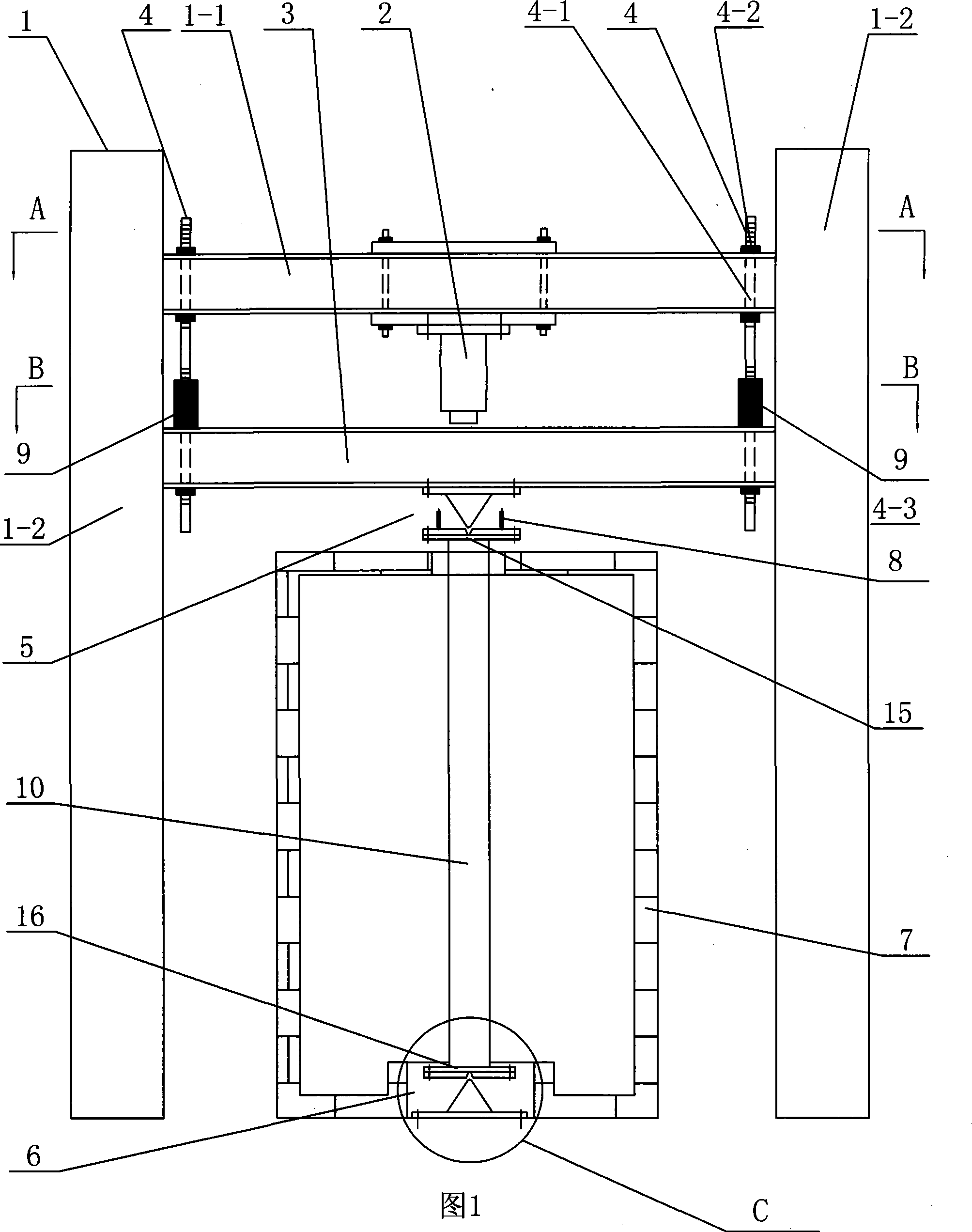
Anti-fire test device of restrained column
A test device and restraint beam technology, applied in the direction of measuring devices, material inspection products, machine/structural component testing, etc., can solve the problems of not considering the fire resistance of columns, insufficient fire protection measures, and different restraint stiffness, etc., to achieve improvement Active fire resistance, remarkable effect and low cost
- Summary
- Abstract
- Description
- Claims
- Application Information
AI Technical Summary
Problems solved by technology
Method used
Image
Examples
specific Embodiment approach 1
[0007] Specific embodiment 1: As shown in Figures 1 to 5, the restraint column fire resistance test device of this embodiment includes a loading reaction frame 1 and a jack 2. The test device also includes a column top restraint beam 3 and two restraint rods 4. The upper support 5, the lower support 6, the furnace body 7 and at least two displacement sensors 8, the jack 2 is installed on the reaction frame top beam 1-1 of the loading reaction frame 1, and the column top restraining beam 3 Horizontally arranged in the loading reaction frame 1 and parallel to the reaction frame top beam 1-1 of the loading reaction frame 1, the jack 2 is located between the reaction frame top beam 1-1 and the column top restraining beam 3, and the column top is restrained There are gaps between the end faces of the beam 3 and the columns 1-2 on both sides of the loading reaction frame 1, the reaction frame top beam 1-1 and the column top restraining beam 3 are connected by two restraining rods 4, and...
specific Embodiment approach 2
[0009] Specific embodiment 2: As shown in Figures 1 to 5, the test device of this embodiment further includes a column upper end plate 15 and a column lower end plate 16. The upper support 5 and the lower support 6 may be knife-edge hinged supports respectively The knife-edge hinged support is connected to the upper end surface of the test restraint column 10 through the upper end plate 15 of the column, and the knife-edge hinged support is connected to the lower end surface of the test restraint column 10 through the lower end plate 16 of the column.
specific Embodiment approach 3
[0010] Specific embodiment 3: As shown in Figs. 1 to 5, in this embodiment, both the upper support 5 and the lower support 6 can be column ends fixedly connected end plates.
PUM
 Abstract
Description
Claims
Application Information
 - R&D
- Intellectual Property
- Life Sciences
- Materials
- Tech Scout
- Unparalleled Data Quality
- Higher Quality Content
- 60% Fewer Hallucinations
Browse by: Latest US Patents, China's latest patents, Technical Efficacy Thesaurus, Application Domain, Technology Topic, Popular Technical Reports.
© 2025 PatSnap. All rights reserved.Legal|Privacy policy|Modern Slavery Act Transparency Statement|Sitemap|About US| Contact US: help@patsnap.com


