Optical transmission system and optical repeater
A relay device and optical transmission technology, applied in transmission systems, electromagnetic wave transmission systems, electromagnetic repeaters, etc., can solve problems such as increased cost and inability to be easily adopted
- Summary
- Abstract
- Description
- Claims
- Application Information
AI Technical Summary
Problems solved by technology
Method used
Image

Examples
no. 1 approach
[0061] Hereinafter, embodiments of the present invention will be described in detail with reference to the drawings.
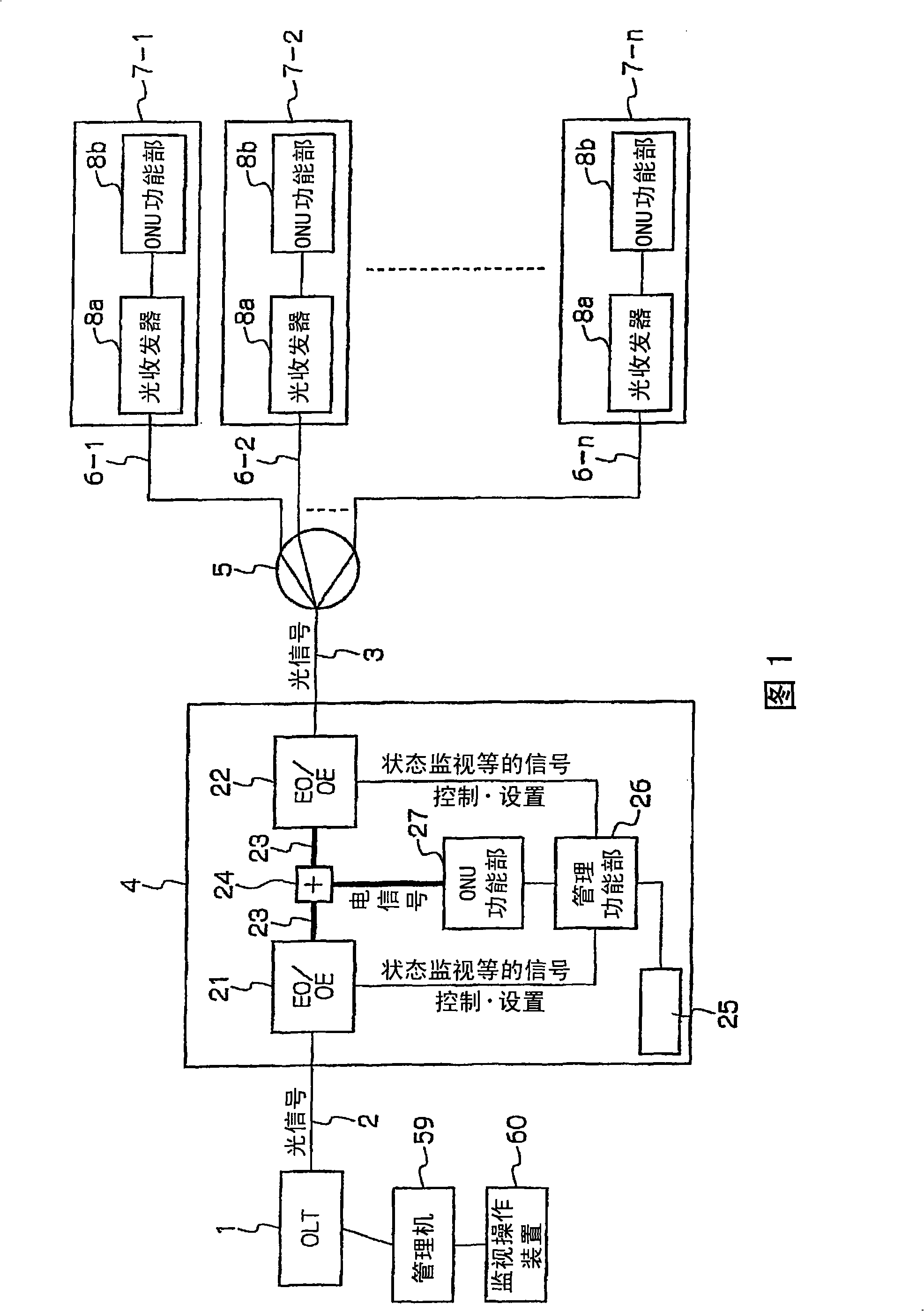
[0062] FIG. 1 is a configuration diagram of a PON-type optical transmission system according to a first embodiment of the present invention.
[0063] In FIG. 1 , a CATV or the like has an optical transmission line having optical fibers 2 and 3 connected to an optical line terminal (OLT) 1 on the center side, and is connected to an optical coupler 5 via an optical relay device 4 . Optical coupler (optical multiplexer and demultiplexer) 5 is split into multiple optical transmission paths through optical fibers 6-1, ... 6-n and optical line terminal units (ONU) 7-1, ... 7 of multiple user residences -n (n is a natural number) connected. The ONUs 7-1, ... 7-n each consist of an optical transceiver 8a and an ONU function 8b connected thereto.
[0064] Here, the term ONU generally includes the function of an optical transceiver. However, when describing the presen...
no. 2 approach
[0091] FIG. 5 is a block diagram showing a configuration of an optical relay device used in an optical transmission system according to a second embodiment of the present invention, showing a configuration that further embodies the optical relay device 4 shown in FIG. 1 . In FIG. 5 , the same reference numerals as in FIG. 1 denote the same elements.
[0092] In Fig. 5, the electric line 23 connecting the first EO / OE part 21 and the second EO / OE part 22 has a first electric line 23a for transmitting electrical signals in the downstream direction and a second electric line 23b for transmitting electric signals in the upward direction . A first electric signal connection part 61 for branching electric signals to the ONU function part 27 and the drive circuit 68 is connected in the middle of the first electric line 23 a. A second electrical signal connection unit 62 that multiplexes an output electrical signal of a predetermined channel output from the ONU function unit 27 to an ...
no. 3 approach
[0107] FIG. 6 is a diagram showing an optical transmission system according to a third embodiment of the present invention, and the same reference numerals as in FIG. 1 denote the same elements.
[0108] In Fig. 6, a plurality of optical relay devices 4-1, ... 4-m with the same structure as the optical relay device 4 shown in Fig. 1 are connected via optical fiber 2a between OTL1 and optical coupler 5, by making the number Further long-distance optical transmission can be realized by increasing.
[0109] Thus, there is no need to install electrical communication lines for the management of the optical relay devices 4-1, ... 4-m, or to install light with different wavelengths from the optical relay devices 4-1, ... 4-m for management. In the case of the transmission path, in the installation of another dedicated line for management, the ONU function unit 27 of electrical signals can multiplex the management signal to the existing PON optical transmission path.
[0110] The ONU...
PUM
 Abstract
Description
Claims
Application Information
 - R&D
- Intellectual Property
- Life Sciences
- Materials
- Tech Scout
- Unparalleled Data Quality
- Higher Quality Content
- 60% Fewer Hallucinations
Browse by: Latest US Patents, China's latest patents, Technical Efficacy Thesaurus, Application Domain, Technology Topic, Popular Technical Reports.
© 2025 PatSnap. All rights reserved.Legal|Privacy policy|Modern Slavery Act Transparency Statement|Sitemap|About US| Contact US: help@patsnap.com