
Lifting hook with chain length reducer

A technology of hooks, closing devices, applied in the direction of chain hooks, chain clasps, chain elements, etc.

Inactive Publication Date: 2009-04-01
FORDE LEMINEE
View PDF8 Cites 11 Cited by
  • Summary
  • Abstract
  • Description
  • Claims
  • Application Information

AI Technical Summary

Problems solved by technology

However, the mandatory use of protective gloves makes this delicate, given the position and size of the pivoting fingers

Method used


Image

  • Lifting hook with chain length reducer
  • Lifting hook with chain length reducer
  • Lifting hook with chain length reducer

Examples


Embodiment Construction

[0016] The hook 1 according to the invention can be used in particular for lifting and moving loads using a lifting gear such as a bridge crane. according to figure 1 and figure 2 In the preferred and non-limiting embodiment shown, the hook 1 comprises a hooked part 3 intended to lift the load directly or by using an intermediate eye (not shown) attached to the load to be lifted. Hook on the load.

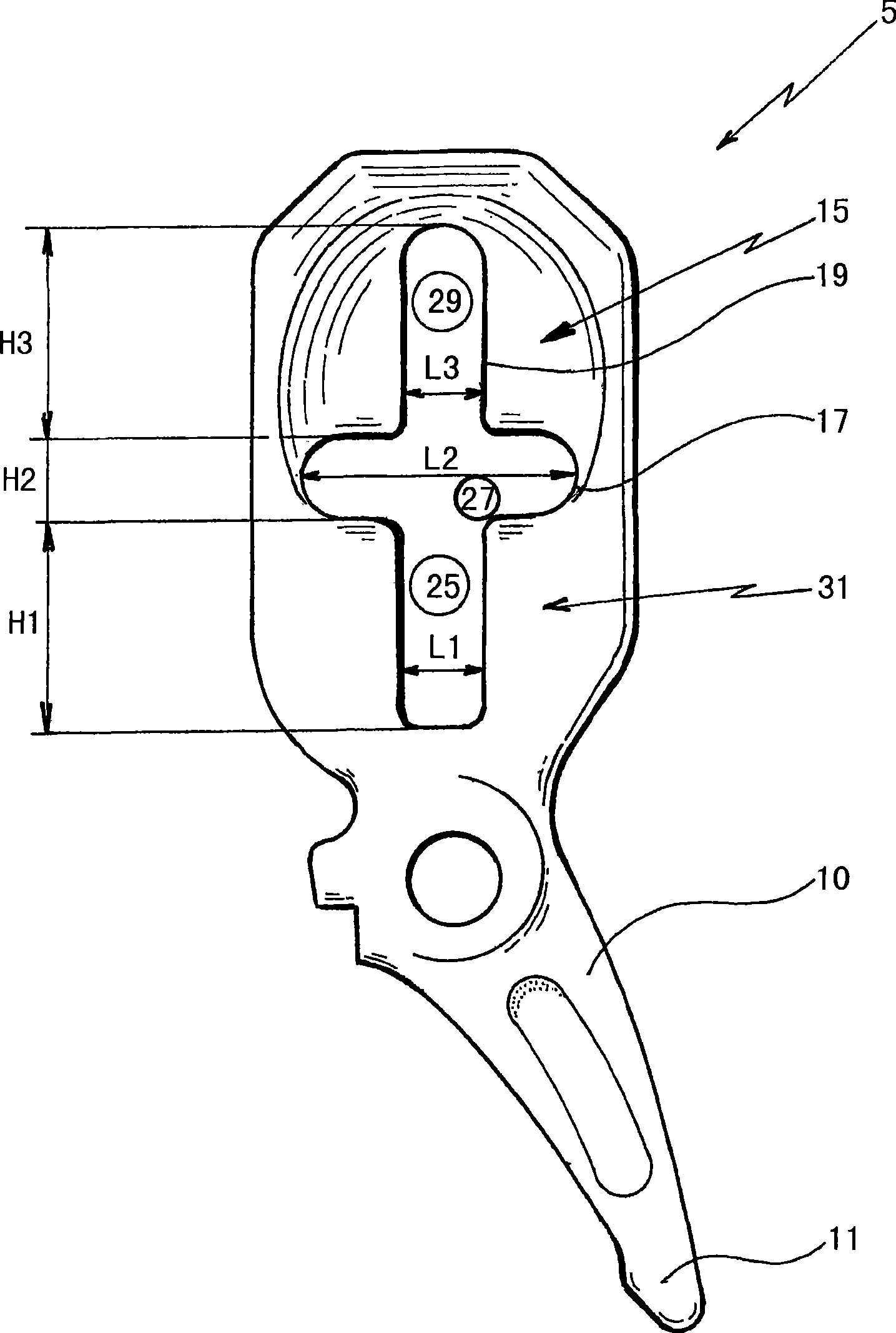
[0017] The hook 1 comprises an adjustable chain 7 and a length reduction device 5 hinged on the upper end 8 of the hook-like part 3 and connected to a traction chain 7 which is wound, for example, on an electric winch drum (without shown) on. According to a preferred embodiment, the reducing device 5 is hinged directly on the upper end 8 using a pivot link 9 .

[0018] The reduction device 5 comprises a closure finger 10 of the hook part 3 . The finger 10 extends towards the bottom end of the reduction device 5 below the pivoting link 9 until the end 11 of the finger 10 rests...


PUM


Abstract

The present invention relates to a lifting hook (1) that can be used to lift loads using lifting gear, comprising a hook-shaped part (3) which hooks onto the load that is to be lifted and a chain length reducer (5) secured to the hook, the said reducer (5) comprising, on the one hand, an orifice (17) the dimensions of which allow the links of the chain (7) to pass through and then allow one (13) of the said links to be locked in position when the said chain (3) is taut and, on the other hand, means (21) for partially closing off the orifice (17) which are hinged so that they can be released manually simply by pressing them so as to allow the length of the chain (7) to be adjusted, notable in that the reducer (5) comprises a closure finger (10) that closes off the hook-shaped part (3) to prevent the load from becoming unhooked, and in that the closing-off means (21) comprise self-locking means (24) which hold the closure finger (10) in the locked position on the part (3) of the hook as long as the closing-off means (21) are disengaged from the orifice (17) and have not yet been returned to a position in which they bear against the external face (23).

Description

technical field [0001] The present invention relates to a load hook which may be used in particular for lifting loads, such as large metal parts, engines, machines and the like. Background technique [0002] Hooks are often used to lift components having a huge mass of up to several hundred kilograms, or even several tons. These components are typically moved using an overhead crane that includes a lifting device that includes a drag chain and an electric winch that can raise and lower the chain to lift the components and can move the components. The chains are connected to hooks, which hook, for example, on eyelets connecting the parts, so that they can be gripped. [0003] It is known to use a chain length reducing device to maximize the elongation of the chain before it is subjected to the tension generated by the lifting load. In this way, severe impacts on the hook, chain and electric winch caused by the winding speed of the chain on the drum of the winch, which is un...

Claims


Application Information

Patent Timeline
IPC IPC(8): F16G15/02
CPCF16G15/02F16G17/00
Inventor 布莱兹·昂里翁
Owner FORDE LEMINEE
Learn More