
Pedal force sensing system of electric booster bicycle

A technology of electric power-assisted bicycles and sensing systems, which is applied to vehicle components, vehicle gearboxes, rider drives, etc., can solve problems such as complex mechanical structures, inconvenient maintenance, and easy to cause danger, so as to improve safety and maintenance Convenience and the effect of reducing the number of wires

Inactive Publication Date: 2009-04-01
J D COMPONENTS CO LTD
View PDF0 Cites 5 Cited by
  • Summary
  • Abstract
  • Description
  • Claims
  • Application Information

AI Technical Summary

Problems solved by technology

[0004] However, there are still some shortcomings in the above-mentioned sensing mode. In terms of sensing the rotational speed of the driving gear, when the user does not apply any pedal force, the driving gear will still continue to rotate. When stepping on the bicycle, the system will not immediately stop supplying the power of the motor, which is relatively easy to cause danger; on the other hand, in terms of sensing the bearing pressure of the wheel shaft, the mechanical structure of its installation is relatively complicated, and it is relatively difficult to maintain. Inconvenient; therefore, known techniques still need to be improved

Method used


Image

  • Pedal force sensing system of electric booster bicycle
  • Pedal force sensing system of electric booster bicycle
  • Pedal force sensing system of electric booster bicycle

Examples


Embodiment Construction

[0024] In order to better understand the characteristics and effects of the present invention, the following examples are given and described as follows in conjunction with the accompanying drawings:

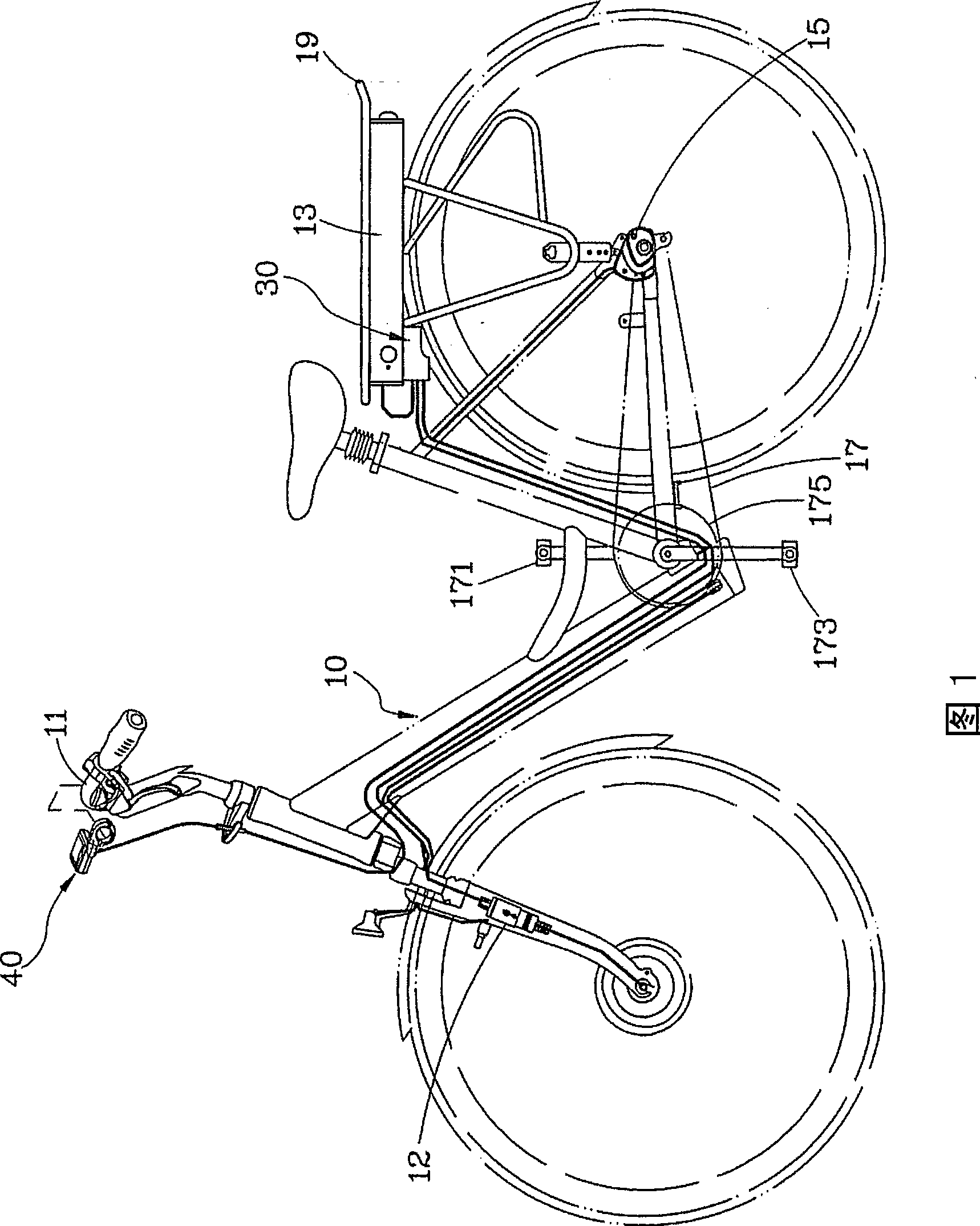
[0025] FIG. 1 is a schematic view of the appearance of a preferred embodiment of the present invention, showing the location of the present invention on a bicycle.

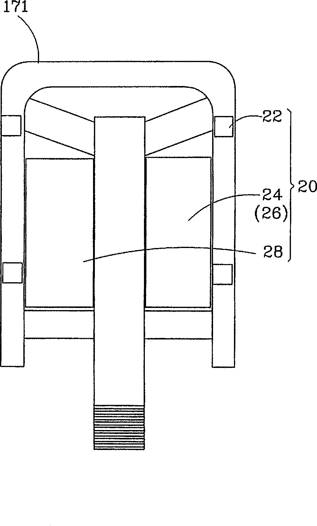
[0026] figure 2 It is a partial plan view of a preferred embodiment of the present invention.

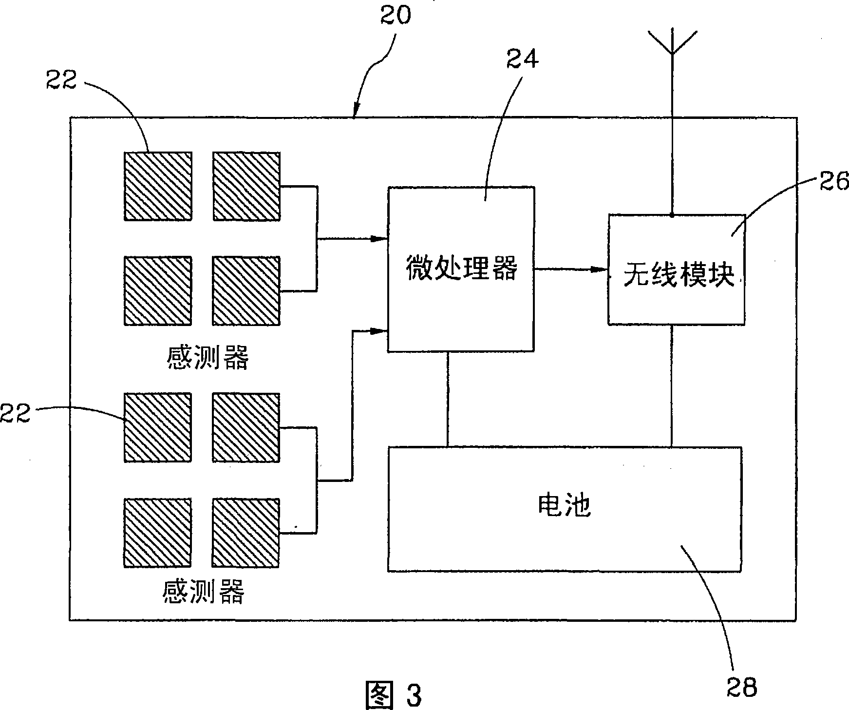
[0027] Fig. 3 is a schematic diagram of electric control of a preferred embodiment of the present invention.

[0028] Fig. 4 is a schematic diagram of electric control in another preferred embodiment of the present invention.

[0029] First of all, please refer to Fig. 1 to Fig. 3, the present invention is a pedal force sensing system of an electric assist bicycle, which is installed on a bicycle body 10, and the body 10 includes a rider frame 11, a front fork shock absorber 12. A battery 13, a driving motor 15, a peda...


PUM


Abstract

The invention provides a pedal force sensing system of a motorized bicycle. The pedal force sensing system is arranged in a motorized bicycle. The bicycle comprises a bicycle body, at least one shock absorber, a battery, a drive motor and a pedal drive mechanism. The pedal drive mechanism is provided with a first pedal and a second pedal which bears the pedal force and drive a pedal shaft to turn. The pedal force sensing system comprises a pedal force sensing set with a plurality of sensors which are arranged on the first pedal of the pedal drive mechanism to sense the pedal force borne by the first pedal; a main controller which is electrically connected with the battery, the drive motor and the shock absorber and receives the pedal force sensing signal of the pedal force sensing set so as to further control the operation of the drive motor and the shock absorption travel of the shock absorber according to the pedal force sensing signal. The pedal force sensing system can increase safety of driving the motorized bicycle, and more accurately sense the pedal force.

Description

technical field [0001] The invention relates to an electric assist bicycle, in particular to a pedal force sensing system of the electric assist bicycle. Background technique [0002] Under the influence of rising oil prices, energy-saving vehicles have become the focus of the public. Among them, electric-powered electric bicycles have the advantages of no pollution and low energy consumption. Therefore, in recent years, whether electric bicycles are used Vehicles used for fitness, leisure or short-distance transportation have become more and more popular in the market. [0003] Generally speaking, electric assist bicycles determine the power supply of the motor according to the user's pedaling force and the assist ratio mode set by the system, so electric assist bicycles must be equipped with a pedaling force sensing system to sense the user's pedaling force In the known technology, the industry mainly installs various sensors on the drive gear or the rear wheel axle to se...

Claims


Application Information

Patent Timeline
IPC IPC(8): B62M23/02B62M6/50
Inventor 梁洽鑫
Owner J D COMPONENTS CO LTD
Learn More