
Electromagnetic hydraulic valve type spring hydraulic operating mechanism having self-defense capability

An operating mechanism and spring hydraulic technology, applied in the field of power transmission and transformation, can solve problems such as large errors, inability of the mechanism to store energy normally, failure to meet the operating conditions of the circuit breaker, etc.

Active Publication Date: 2009-03-25
沈阳广驰工大高压电气有限公司
View PDF0 Cites 22 Cited by
  • Summary
  • Abstract
  • Description
  • Claims
  • Application Information

AI Technical Summary

Problems solved by technology

However, due to the arc factor and the mechanical connection gap error of the auxiliary switch and the micro switch, the closing-opening time is unstable, the error is large, and the reliability is low. The closing-opening time error is greater than 6ms, which cannot meet the requirements of the circuit breaker. The operating condition that the three-phase period is not greater than 3ms (required by the State Grid) during the second opening of the reclosing operation
However, the existing spring hydraulic operating mechanism adopts three energy storage cylinders as a split structure. Due to the influence of the radial component force of the disc reed, the force is uneven, and the radial component force is likely to cause a single energy storage piston and The energy storage cylinder is stuck, so that the energy storage piston cannot move, and the sealing ring is easily damaged and leaks oil. If one energy storage cylinder fails to work, it will cause eccentric force on the disc reed group, so that the mechanism cannot store energy normally.

Method used


Image

  • Electromagnetic hydraulic valve type spring hydraulic operating mechanism having self-defense capability
  • Electromagnetic hydraulic valve type spring hydraulic operating mechanism having self-defense capability
  • Electromagnetic hydraulic valve type spring hydraulic operating mechanism having self-defense capability

Examples


Embodiment

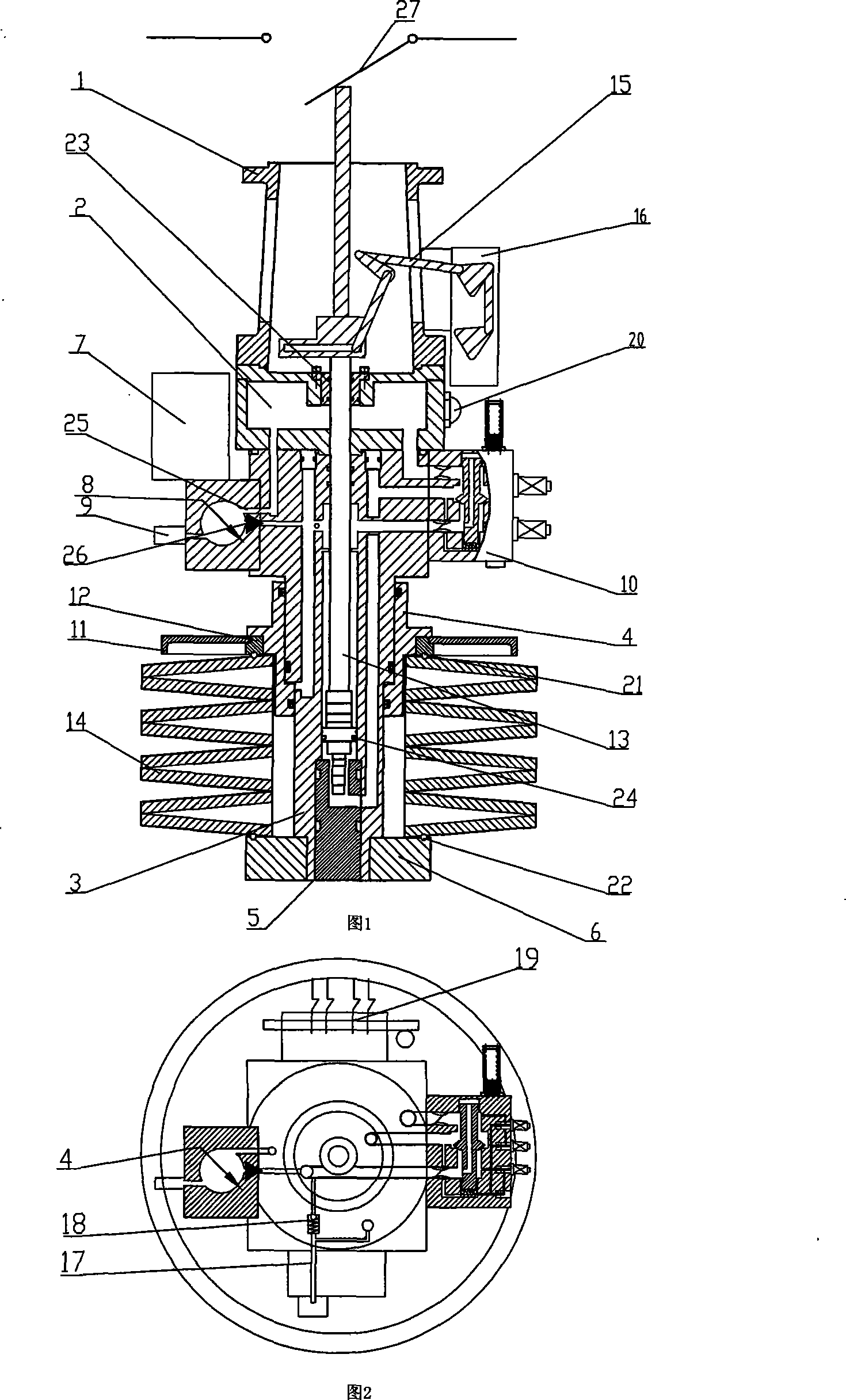
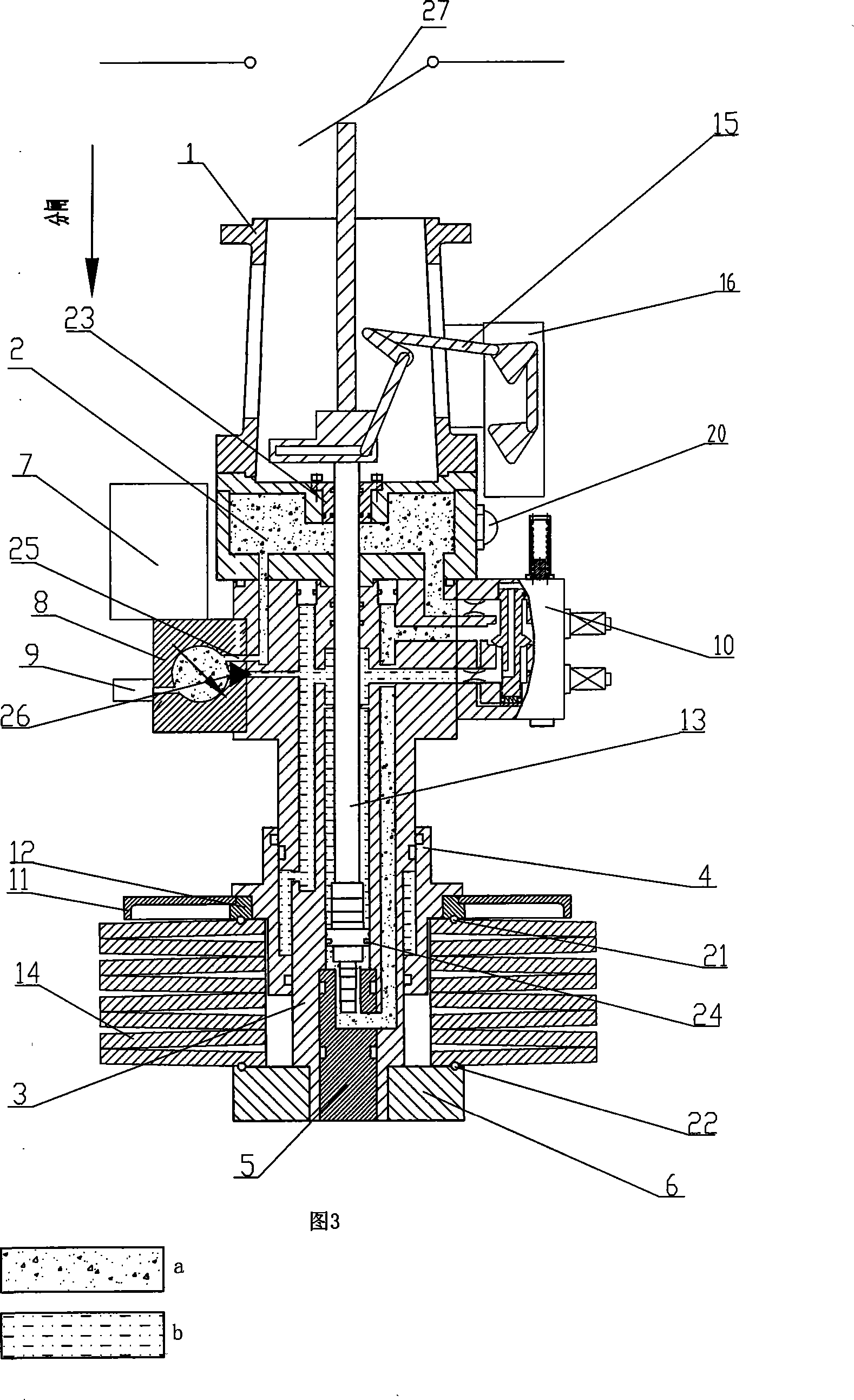
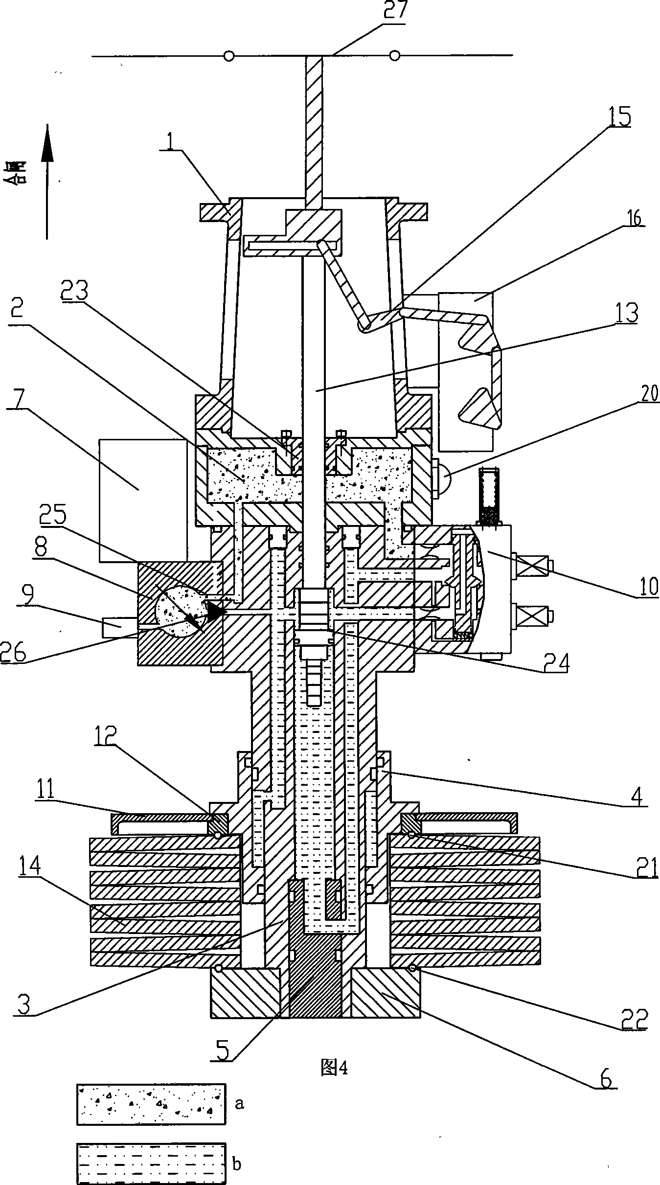
[0082] The spring hydraulic operating mechanism with self-defense capability is shown in Figure 1, Figure 2, Figure 5 , Figure 6 , Figure 7 , Figure 8 , Figure 9 and Figure 10 As shown, the side of the support 1 is connected to the auxiliary switch 16, the lower end of the support 1 is fixed on the low-pressure fuel tank 2, the side of the low-pressure fuel tank 2 is provided with an oil mark 20, the bottom end of the low-pressure fuel tank 2 is sealed and connected to the working cylinder 3, and the upper end of the working cylinder 3 The outer surface is connected with the oil pump 8 , the electromagnetic hydraulic valve 10 and the safety relief valve 17 , wherein the oil pump 8 is connected with the working cylinder 3 through the oil pump connection groove 36 . The oil tank pump interface of the low-pressure oil tank 2 communicates with the upper opening of the oil pump channel of the working cylinder 3, the oil tank low-pressure oil interface of the low-pressure o...


PUM


Abstract

An electromagnetic hydraulic valve type spring hydraulic operation mechanism with the ability of self-protection belongs to the technical field of electric transmission and transformation. The operation mechanism includes a support, a low pressure oil tank, an oil pump motor, an oil pump, a disc reed group, a working cylinder body, an working cylinder piston, an energy storage piston cylinder, an auxiliary switch, an auxiliary switch connecting rod, an electromagnetic hydraulic valve, a safety relief valve, a travel switch, a bottom board, a base, a round plate and a pressure plate, wherein the electromagnetic hydraulic valve connected with the working cylinder of the operation mechanism is an electromagnetic hydraulic valve with the ability of self-protection. The electromagnetic hydraulic valve type spring hydraulic operation mechanism capable of self-protecting integrates the electromagnetic hydraulic valve with the ability of self-protection into the spring hydraulic operation mechanism to satisfy the requirement of self-protection of national power grid to breakers, and the running is stable and the error is small under the condition that the time of switching-off operation is set.

Description

technical field [0001] The invention belongs to the technical field of power transmission and transformation, in particular to an electromagnetic hydraulic valve type spring hydraulic operating mechanism with self-defense capability. Background technique [0002] With the continuous growth of power system capacity and the technological advancement of high-voltage circuit breakers, the requirements for the opening and closing time of high-voltage circuit breakers are getting smaller and smaller. The State Grid requires that high-voltage circuit breakers should have self-defense capabilities. The closing and opening operations of high-voltage circuit breakers It is accomplished by the operating mechanism, that is, the operating mechanism should have the function of self-defense capability. The electromagnetic hydraulic valve adopted by the spring hydraulic operating mechanism has a unique close-open delay technology, which makes the spring hydraulic operating mechanism have th...

Claims


Application Information

Patent Timeline
IPC IPC(8): H01H33/34H01H3/24
Inventor 周宇政李声富英
Owner 沈阳广驰工大高压电气有限公司
Learn More