
Magnetic force hoisting roof

A lifting jack and magnetic technology, applied in the direction of lifting devices, etc., can solve the problems of sticky oil on the casing, troublesome use of the jack, and pollute the human body, and achieve the effect of not easy pollution and simple structure.

Inactive Publication Date: 2009-03-25
郑强
View PDF0 Cites 5 Cited by
  • Summary
  • Abstract
  • Description
  • Claims
  • Application Information

AI Technical Summary

Problems solved by technology

[0002] Nowadays, jacks are generally used when lifting heavy objects upwards, but the use of the jack is troublesome, and because of the internal oil, it is easy to cause the shell to stick with oil and pollute the human body

Method used


Image

  • Magnetic force hoisting roof

Examples


Embodiment Construction

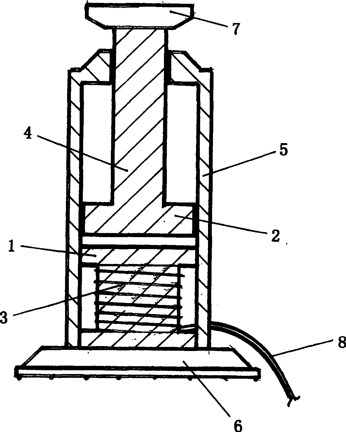
[0009] In the figure: the electromagnet 1 is installed in the shell connected to the base 6 and the inner bottom, and the power cord 8 connected to the outer coil 3 passes through the shell 5, and the ejector rod 4 connected to the magnet block 2 installed above the electromagnet 1 Attach a flat header 7 through the top of the housing.

[0010] The electromagnet 1 of adorning in its housing 5 and the magnet block 2 are oppositely arranged for the same pole.


PUM


Abstract

The invention provides a magnetic raising-power elevator. An electromagnet is arranged under a casing connected with a seat. An outer-wound coiled power-supply wire is threaded through the casing; a magnet block provided with the same magnetism as the electromagnet is oppositely arranged on the lower part of the electromagnet and the connected top part is threaded through the top of the casing to be connected with a flat top part. The invention adopts the like-pole repulsion theory to oppositely arrange the electromagnet and magnetic block which are provided with the same magnetism, after the electromagnet is switched on power and generates magnetic power the upper magnet block is driven to rise to generate the raising power used for elevating common objects.

Description

Technical field [0001] The invention relates to a device for lifting and jacking up objects, in particular to a magnetic lifting jack. Background technique [0002] Now when promoting upwards to jack up bulky objects, jacks are generally used, but the use of the jacks is cumbersome, and because of the built-in organic oil, it is easy to cause the shell to stick to the oily dirt and pollute the human body. Contents of the invention [0003] The invention provides a magnetic lifting top, which has the characteristics of simple structure and no pollution. [0004] The invention includes an electromagnet, a magnet block, a coil, a casing, a base and a power cord, and the adopted technical solution is: an electromagnet is installed in the lower part of the casing connected to the base, and the power cord connected to the outer winding coil goes out of the casing The ejector rod connected with the magnet block installed above the electromagnet passes through the top of the shel...

Claims


Application Information

Patent Timeline
Patent Type & Authority Applications(China)
IPC IPC(8): B66F3/00
Inventor 郑强
Owner 郑强
Learn More