Top clamp type side shielding apparatus for electroplating printed circuit board

A technology for printed circuit boards and shielding devices, applied in the directions of printed circuits, printed circuit manufacturing, electrical components, etc., can solve the problems of material, labor and power waste, increasing the thickness deviation of plating settings, and wasting copper.

Active Publication Date: 2009-02-25
WUS PRINTED CIRCUIT (KUNSHAN) CO LTD
View PDF0 Cites 6 Cited by
  • Summary
  • Abstract
  • Description
  • Claims
  • Application Information

AI Technical Summary

Problems solved by technology

However, this will waste a large amount of copper acting on the ineffectively produced edge material, and cause a waste of materials, manpower and electricity, and will increase the deviation between the thickness of the electroplating set and the actual operation.

Method used


Image

  • Top clamp type side shielding apparatus for electroplating printed circuit board
  • Top clamp type side shielding apparatus for electroplating printed circuit board
  • Top clamp type side shielding apparatus for electroplating printed circuit board

Examples


Embodiment Construction

[0021] The specific embodiment of the present invention is described further in conjunction with accompanying drawing now:

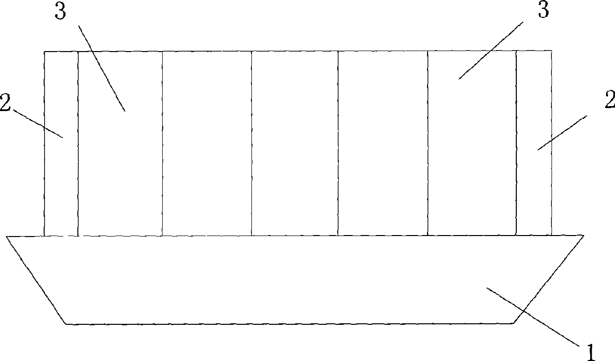
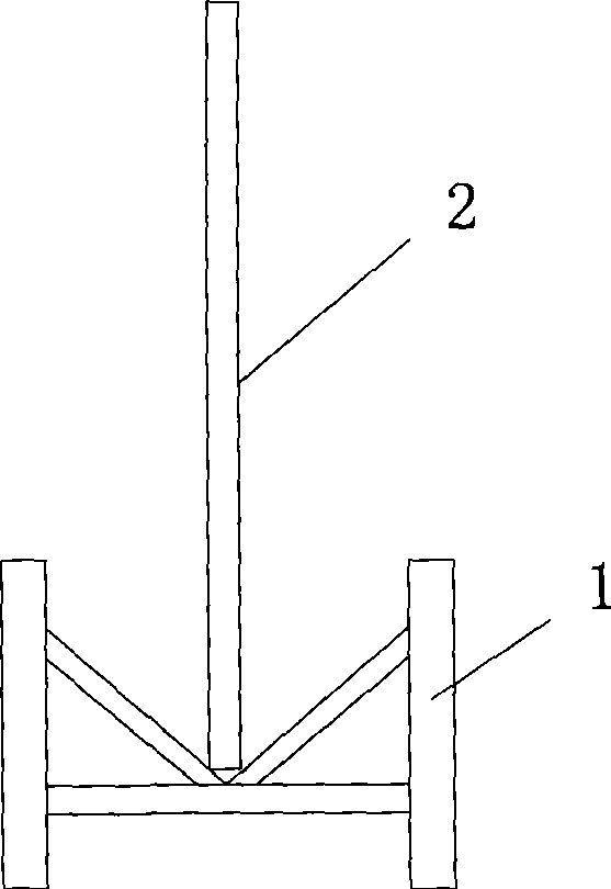
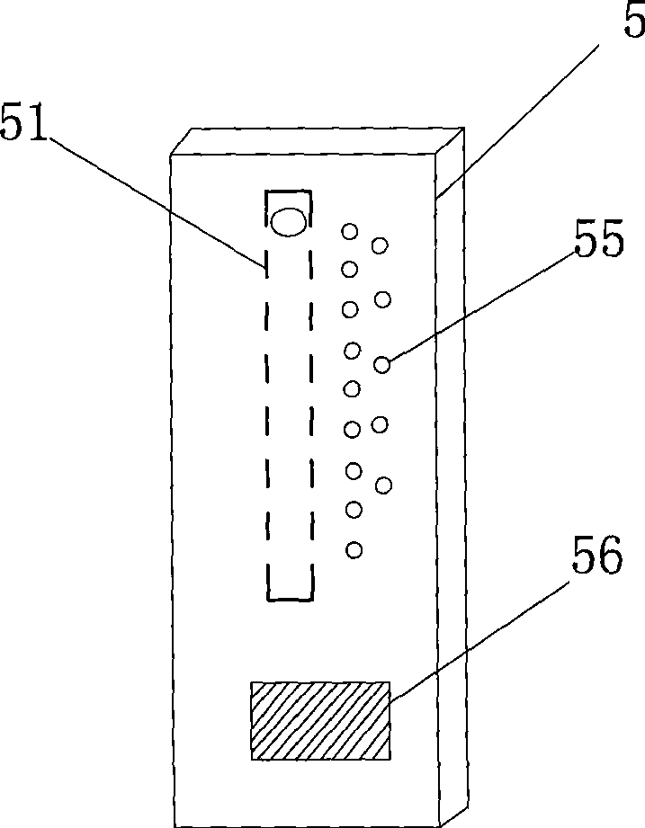
[0022] Figure 4 It is the schematic diagram when the boat-shaped baffle of the present invention floats on the liquid surface, and the boat-shaped baffle 1 floats on the liquid surface 41 of the electroplating solution 4, and now the connecting rod 52 is outwardly opened, and the connecting rod 52 is in an approximately horizontal state; A pair of side baffles 5 are respectively provided at both ends of the ship-shaped baffle 1, and a longitudinal chute 51 is provided on the side baffle 5, and the side baffles 5 are connected with the boat-shaped baffle 1 through a connecting rod 52, and the connecting rod 52 One end is fixedly connected to the boat-shaped baffle 1 through a fixed shaft 53 , and the other end of the connecting rod 52 is movably connected to the chute 51 through a movable shaft 54 ​​. Such as image 3 As shown, the side baffle 5 is fix...


PUM


Abstract

The invention provides an electroplated lateral shielding device for a top-clamp type printed circuit board. Two ends of a ship-shaped baffle are respectively provided with a pair of lateral baffles; each lateral baffle is provided with a sliding chute; the lateral baffles are connected with the ship-shaped baffle by connecting rods; one end of each connecting rod is fixedly connected on the ship-shaped baffle by a fixed shaft, while the other end of each connecting rod is connected on each sliding chute by a movable shaft; and weights leading the lateral baffles to maintain low gravity center are fixed on the lateral baffles. The invention can reduce invalid production, reduce material waste, reduce the partial difference between setting thickness by electroplating and actual operation, and meet the control requirement of electroplating evenness.

Description

technical field [0001] The invention relates to a printed circuit board (PCB) electroplating side shielding device, in particular to a top clip type printed circuit board electroplating side shielding device. Background technique [0002] Due to the difference in the environment of the copper surface of the edge part of the sub-operation window and the central area of ​​the operation window during PCB electroplating, the electroplating copper thickness is uneven. In order to achieve the uniformity of electroplating, some shielding designs must be made at the corresponding positions on the edge of the window. For example, a boat-shaped baffle is provided at the bottom of the window. This invention discusses how to achieve uniformity of electroplating on the side edge of the window. In the electroplating process of printed circuit boards, in order to achieve the uniformity of electroplating on the side edges of the window, the existing practice is: figure 1 , 2 As shown, the...

Claims


Application Information

Patent Timeline
IPC IPC(8): C25D5/02H05K3/18
Inventor 马夕松
Owner WUS PRINTED CIRCUIT (KUNSHAN) CO LTD
Why Eureka
Try Eureka