Method for the transmission of data using self-diagnostic pulse width modulation
A technology of pulse width modulation and transmission of information, applied in transmission systems, digital transmission systems, correct operation tests, etc., capable of solving problems such as overheating, unsatisfactory fault identification, and damage to internal combustion engines
- Summary
- Abstract
- Description
- Claims
- Application Information
AI Technical Summary
Problems solved by technology
Method used
Image
Examples
Embodiment Construction
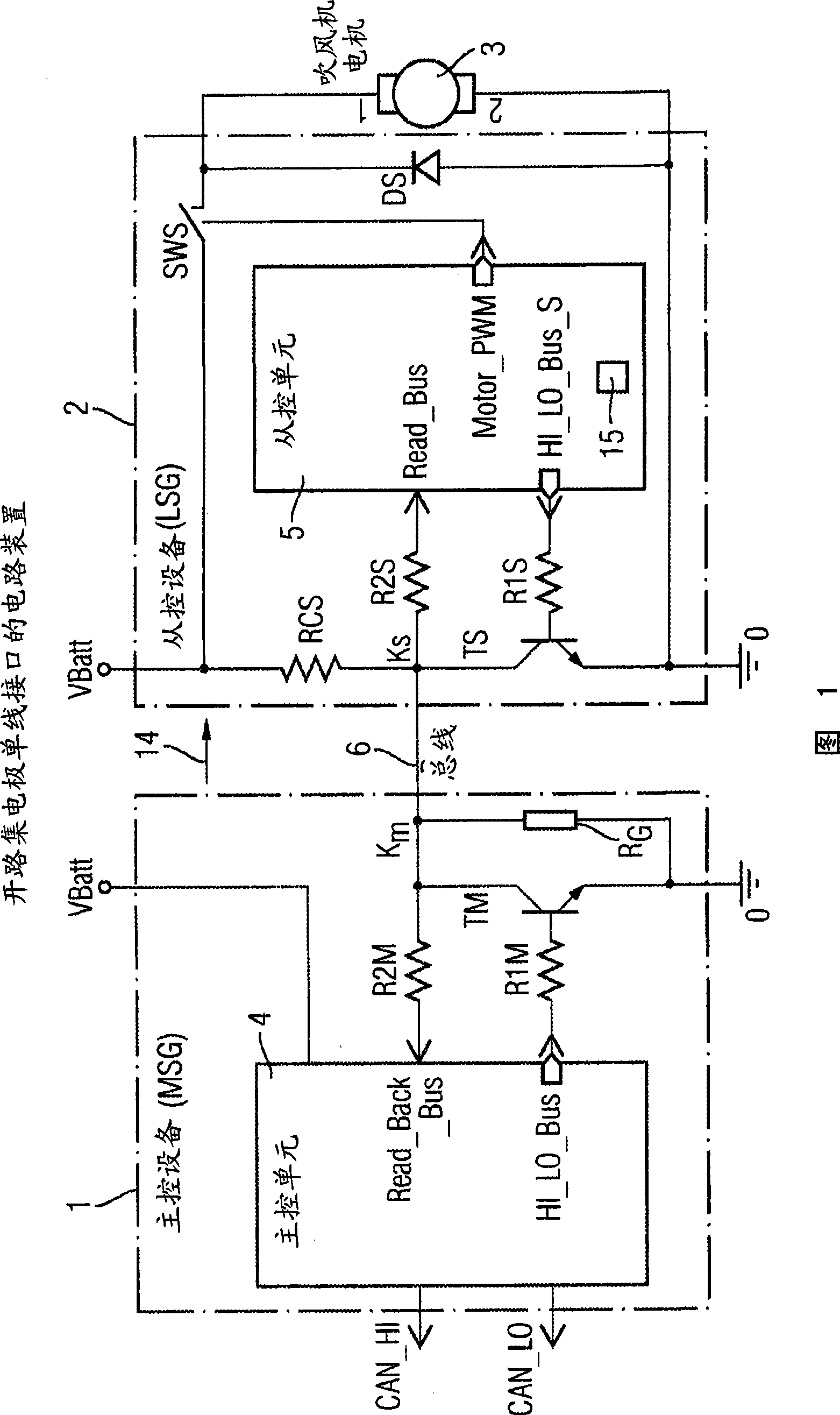
[0025] FIG. 1 shows a schematic diagram of a circuit arrangement commonly used in motor vehicles for controlling the power flow of a fan or an oil pump.
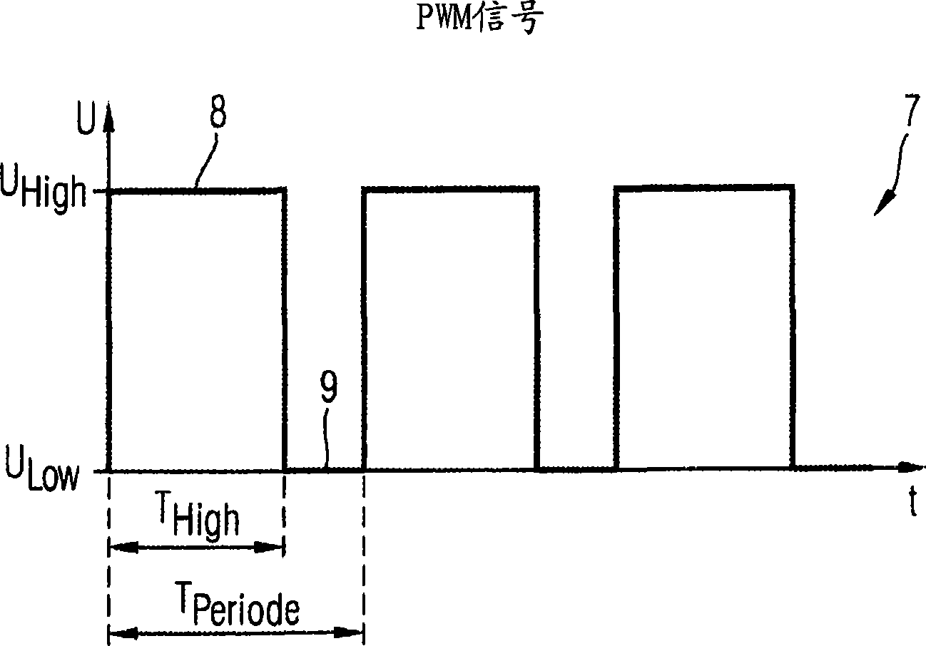
[0026] A master ("MSG") 1 forms a data source connected via a bidirectional bus 6 to a slave ("LSG") 2 (data sink). The two devices 1, 2 are powered by the vehicle battery ("VBatt", "0"). The slave control device 2 controls the ventilator 3 . The master control device 1 has a master control unit 4 which is connected on the input side to the CAN bus (terminals “CAN_HI” and “CAN_LO” in FIG. 1 ). The pulse width modulation signal (referred to below as PWM signal) generated in the main control unit 1 is continuously output at the output terminal ("HI_LO_Bus") and reaches the base of the transistor "TM" via the resistor "R1M". The collector of transistor "TM" is connected to one end of single-wire interface 6 in node "KM". Resistor "RG" connects node "KM" to the ground (0) of the car battery. The other end of the single-wire ...
PUM
 Abstract
Description
Claims
Application Information
 - Generate Ideas
- Intellectual Property
- Life Sciences
- Materials
- Tech Scout
- Unparalleled Data Quality
- Higher Quality Content
- 60% Fewer Hallucinations
Browse by: Latest US Patents, China's latest patents, Technical Efficacy Thesaurus, Application Domain, Technology Topic, Popular Technical Reports.
© 2025 PatSnap. All rights reserved.Legal|Privacy policy|Modern Slavery Act Transparency Statement|Sitemap|About US| Contact US: help@patsnap.com


