
Dip laneway digging hole layout mode

A roadway and blasthole technology, which is applied in the field of drilling and blasting, can solve the problems that the rock blocks cannot be effectively thrown away after the blasting, and the blasting efficiency of the downhill roadway is low, so as to achieve the effect of speeding up the cycle footage, improving the blasting efficiency, and increasing the tunneling speed

Inactive Publication Date: 2011-07-27
山东科技大学科技产业总公司
View PDF0 Cites 0 Cited by
  • Summary
  • Abstract
  • Description
  • Claims
  • Application Information

AI Technical Summary

Problems solved by technology

[0003] In order to solve the problem of low blasting efficiency in downhill roadway excavation and rock blocks cannot be effectively thrown away from the working face after blasting, the present invention proposes a new blasthole layout method

Method used


Image

  • Dip laneway digging hole layout mode
  • Dip laneway digging hole layout mode
  • Dip laneway digging hole layout mode

Examples


Embodiment Construction

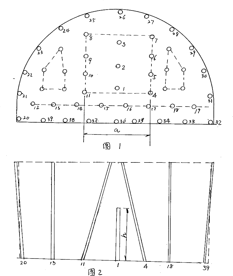
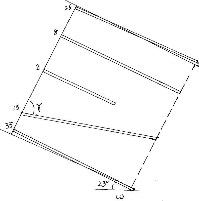
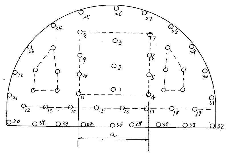
[0009] The embodiment is a downhill roadway with an inclination W=23°. The layout of excavation blastholes is as follows: Figure 1-Figure 3 shown. From figure 1 It can be seen that it has a total of 49 blastholes, of which No. 1-3 are auxiliary straight holes for cutting, and the eye depth h=0.8-1.0 meters; No. 4-7 and No. 8-11 are divided into two rows on the left and right. Wedge-shaped cutting holes are arranged in the middle and upper part of the roadway section, and the distance between two rows is a = 1.0-1.2 meters; No. 12-19 are auxiliary throwing holes, and the drilling direction and the section are at an angle of γ = 85° to drill obliquely upward; Nos. 20-32 are peripheral holes, which are evenly arranged on the two sides and the top contour of the section; No. 33-39 are bottom holes, which are evenly distributed on the bottom contour of the section; the rest of the unnumbered blastholes are auxiliary holes, which are evenly arranged On the space between the cut ...


PUM


Abstract

The invention discloses a mine downhill roadway tunnelling shot hole arrangement way, which comprises cut holes, auxiliary holes, a peripheral hole and a bottom hole, wherein the cut holes are in a wedge arrangement way, and are arranged on the middle upper portion of a roadway cross section, wherein the pitch of two rows of wedge cut holes is larger 30% than the pitch of current wedge cut holes,a row of auxiliary straight holes are arranged between two rows of wedge cut holes, and the width of the auxiliary straight hole is 0.5 time than that of the cut holes, and a row of auxiliary throwing holes are further arranged under the two rows of the cut holes, and the drilling direction of the auxiliary throwing holes is drilled to the oblique upper portion in smaller than 90 degrees with theroadway cross section, and the auxiliary throwing holes are finally detonated with the bottom hole in the same section. The invention fully utilizes the least resistance line principle, reasonably distributes the wedge cut holes, and increases the blasting efficiency and tunnelling velocity.

Description

technical field [0001] The invention belongs to mine excavation technology, in particular to a drilling and blasting method. Background technique [0002] In coal mining, to develop a large number of underground roadways, the drilling and blasting method is generally adopted. Blastholes are generally divided into cutholes, auxiliary holes, peripheral holes, and bottom holes; the arrangement is that the middle and lower parts of the roadway section are cutout holes, and the surroundings of the cutout holes are auxiliary holes (or caving holes), and the top of the section and the contours of the two sides The line is the peripheral eye, and the bottom edge outline is the bottom eye. Since the roadway belongs to single free surface blasting, the cutting eye is the key to the blasting effect. There are many types of cutting holes, including wedge-shaped cutting holes (ie, V-shaped cutting holes), tapered cutting holes and fan-shaped cutting holes. Among them, the wedge-shaped...

Claims


Application Information

Patent Timeline
Patent Type & Authority Patents(China)
IPC IPC(8): F42D1/02F42D3/00
Inventor 王洪立张宪堂陈士海周红敏鲍伟
Owner 山东科技大学科技产业总公司
Learn More