Switch

A switch and moving contact technology, applied in the direction of electrical switches, electrical components, circuits, etc., can solve the problems of the number of components, the number of assembly processes, the inability to switch miniaturization, and the increase in cost, and achieve high production efficiency, high reliability, and high cost. The effect of reducing the number of parts

Active Publication Date: 2009-01-07
OMRON CORP
View PDF1 Cites 7 Cited by
  • Summary
  • Abstract
  • Description
  • Claims
  • Application Information

AI Technical Summary

Problems solved by technology

[0005] However, in the switch structure described above, since the movable terminal 37 needs to be supported by the retaining spring 46 and the return spring 47, the number of parts and the number of assembly steps are large, and the cost increases.
[0006] In addition, since the movable terminal 37 moves with the operation of the button 14, the displacement speed of the movable terminal 37, that is, the opening or closing speed of the contact is approximately equal to the operation speed of the button 14, and the contact cannot be made instantaneously. open or close
As a result, it is necessary to form contacts with a large contact area in order to prevent contact wear when the contacts of large currents are opened or closed, so there is a problem that the size of the switch cannot be reduced.

Method used


Image

  • Switch
  • Switch
  • Switch

Examples


Embodiment Construction

[0085] Next, an embodiment of the present invention will be described with reference to FIGS. 1A, B to 26A, B of the accompanying drawings.

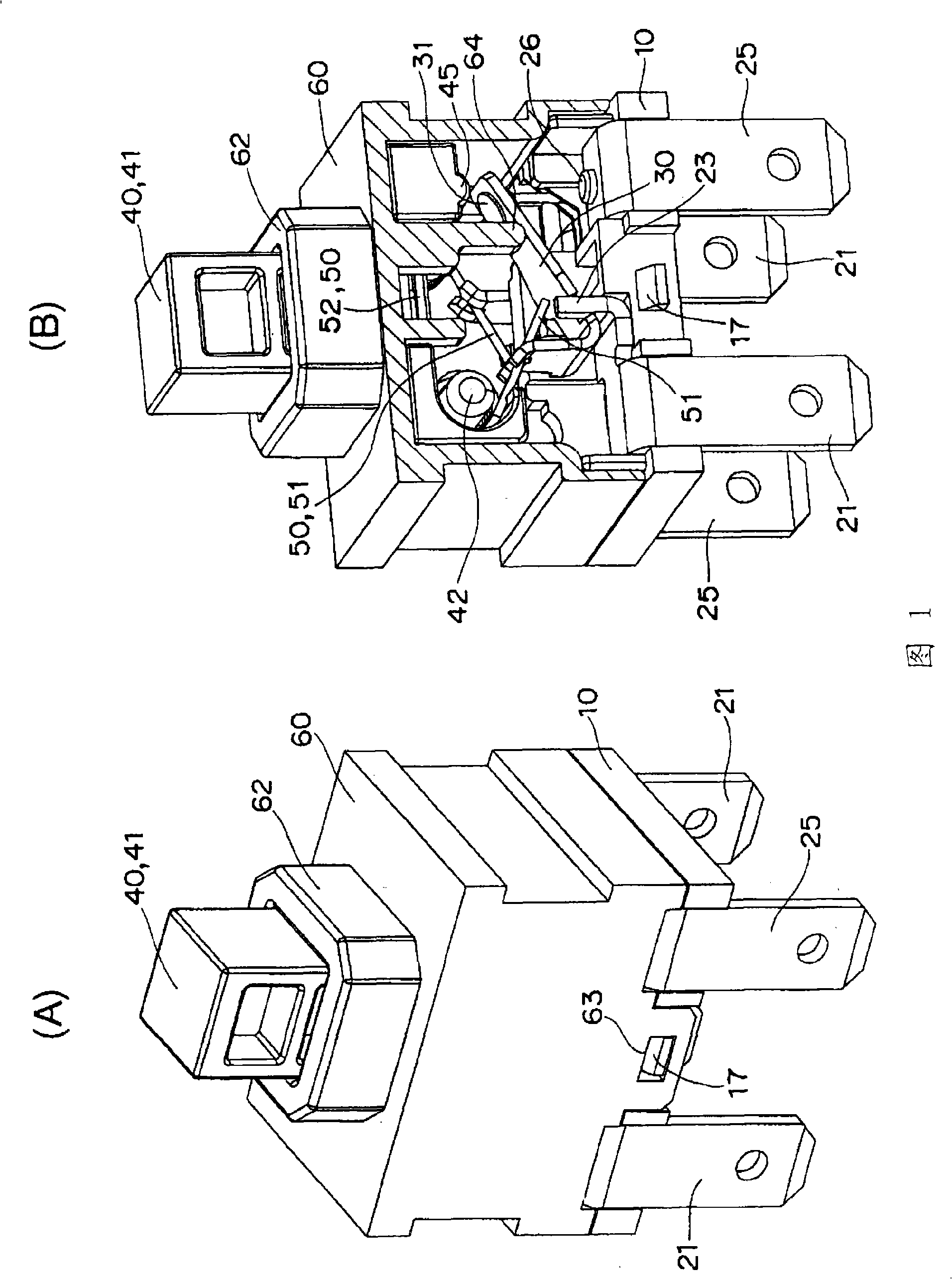
[0086] As shown in Fig. 1A, B~Fig. 8A-E, the switch of the first embodiment has: base 10; Two groups of contact mechanisms 20,20 installed on the base 10; The lock pin 35 operates the push rod 40 of the contact mechanism 20; and the case 60 is fitted in the base 10, covers the contact mechanism 20, and supports the push rod in a vertically movable manner. 40.

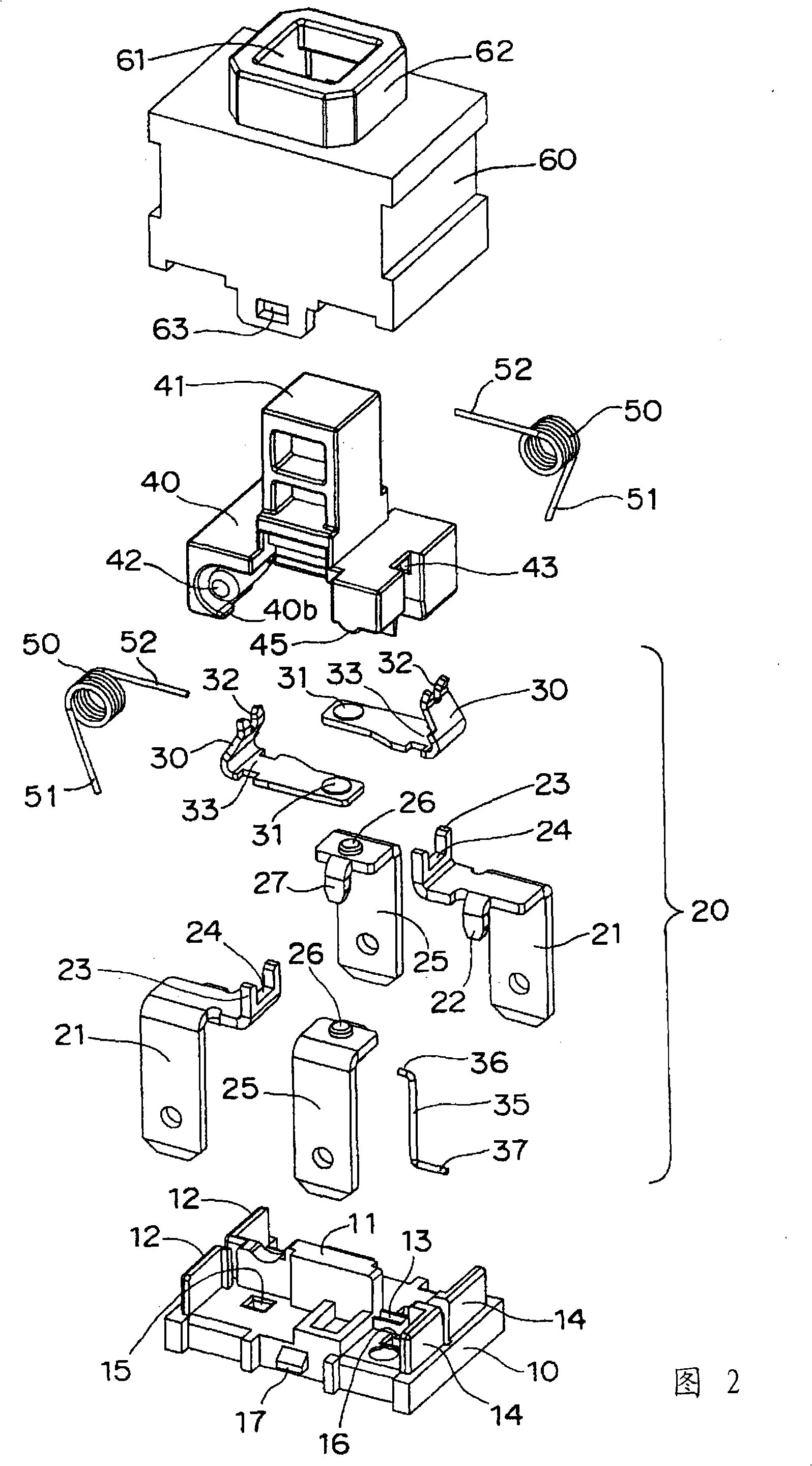
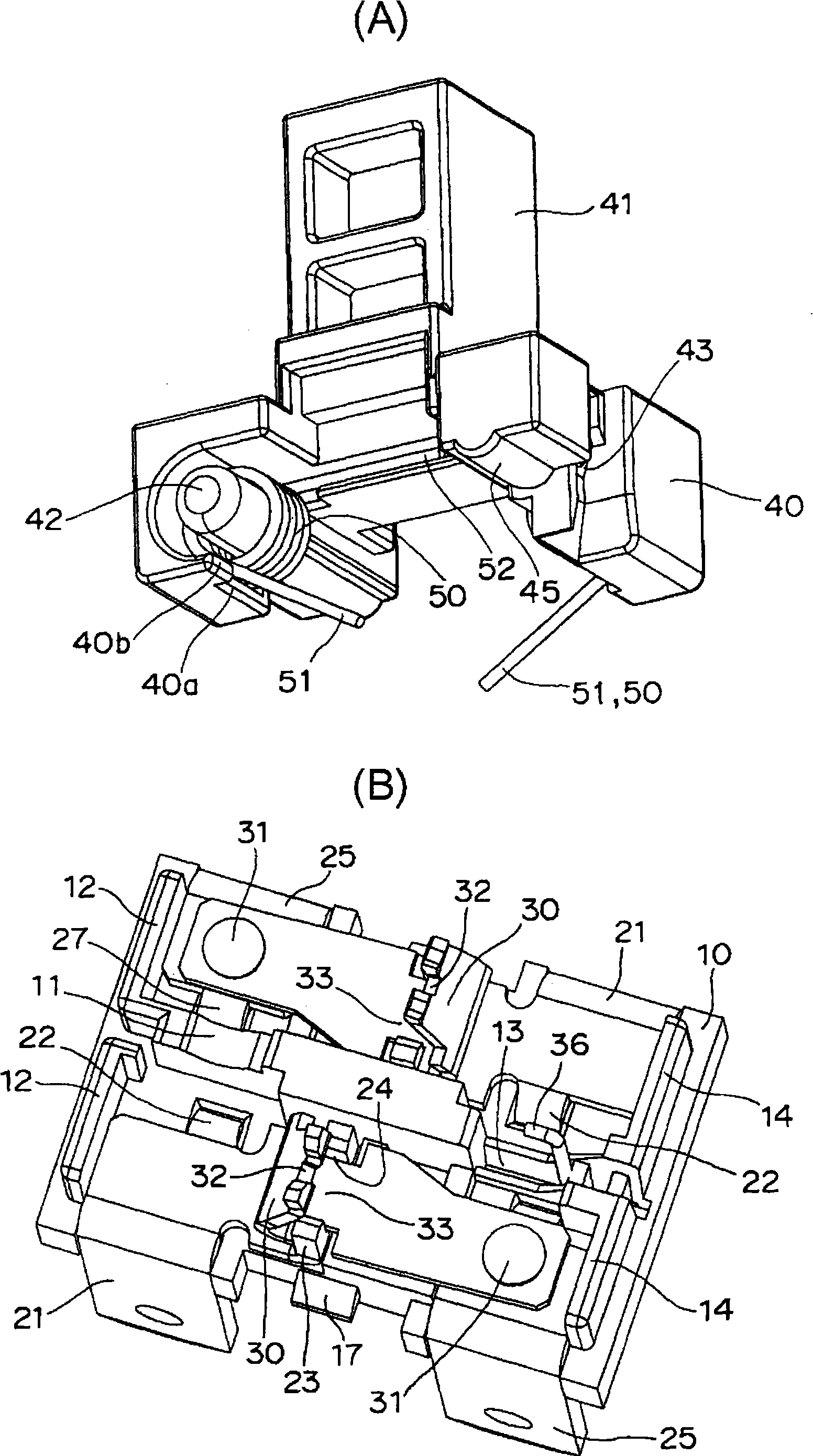
[0087] As shown in FIG. 2, on the base 10, a pair of insulating walls 12, 12 protrude on the same straight line from one end side of the partition wall 11 protruding from the center of the upper surface. An engaging groove 13 is disposed on the extension line of the engaging groove 13, and a pair of insulating walls 14, 14 protrude from the other end side of the engaging groove 13 on the same straight line. In addition, square holes 15 and 16 for press-fitting are respectively p...


PUM


Abstract

The invention provides a compact switch in which a contact can instantaneously be opened and closed while the number of components and assembly man-hour are decreased. The switch includes a support terminal (21) which is assembled in a base (10); a movable contact piece (30) which is made of a belt-like electroconductive material bent into a substantial J-shape in section, the movable contact piece including a movable contact (31) provided in one end portion thereof, an intermediate portion of the movable contact piece being turnably supported by a turning support portion (24) of the support terminal (21); a plunger (40) which is accommodated in an internal space while being able to be vertically moved, the internal space being formed by fitting a housing (60) in the base (10); and a coil spring (50) which is turnably supported by the plunger (40). The plunger (40) is slid while vertically moved to press-contact one end portion (51) of the coil spring (50) against the other end edge portion of the movable contact piece (30), whereby the movable contact piece (30) is reversed to bring the movable contact (31) into contact with a fixed contact (26) or to separate the movable contact (31) from the fixed contact (26).

Description

technical field [0001] The present invention relates to a switch, in particular to a switch capable of opening or closing a contact by pressing. Background technique [0002] Conventionally, as a switch capable of opening or closing a contact by a pressing operation, for example, there is a switch structure described below (see Patent Document 1). [0003] That is, this switch structure is to make the movable terminal 37 reciprocate in the up and down direction by operating the button 14, so that the movable contacts 41, 41 arranged at both ends of the movable terminal 37 are respectively connected to the fixed contacts 45, 41 opposite to the movable terminal 37. 45 contact or separation. [0004] Patent Document 1: (Japanese) Unexamined Patent Publication No. H10-208581 [0005] However, in the switch structure described above, since the movable terminal 37 needs to be supported by the holding spring 46 and the restoring spring 47, the number of parts and the number of as...

Claims


Application Information

Patent Timeline
Patent Type & Authority Applications(China)
IPC IPC(8): H01H13/56H01H13/20H01H13/36
CPCH01H3/001H01H5/16H01H13/562H01H13/30
Inventor 清野泰弘鸣尾俊博
Owner OMRON CORP
Why Eureka
Try Eureka