Damping device and damping method
A technology of vibration damping device and vibration absorber, which is applied in the direction of spring/shock absorber, vibration suppression adjustment, mechanical equipment, etc.
- Summary
- Abstract
- Description
- Claims
- Application Information
AI Technical Summary
Problems solved by technology
Method used
Image

Examples
no. 1 Embodiment approach
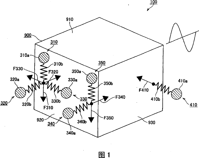
[0063] figure 1 It is a schematic diagram showing an example of the vibration suppressing device 100 according to the first embodiment of the present invention.
[0064] Such as figure 1 As shown, the vibration suppression device 100 includes six dynamic vibration absorbers 310, 320, 330, 340, 350, and 410, and the vibration suppression device 100 is installed on a box-shaped member 900 such as an engine or an electric motor.
[0065] Such as figure 1 As shown, dynamic vibration absorbers 310 , 320 , 330 , 340 , and 350 are provided on surface 920 of box-shaped member 900 of vibration suppressing device 100 , and dynamic vibration absorber 410 is provided on surface 930 of box-shaped member 900 .
[0066] Such as figure 1 As shown, the dynamic vibration absorber 310 is composed of a hammer portion 310a and a spring 310b. In addition, the dynamic vibration absorber 320 is composed of a hammer portion 320a and a spring 320b; the dynamic vibration absorber 330 is composed...
no. 2 Embodiment approach
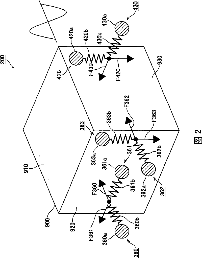
[0075] figure 2 It is a schematic diagram showing an example of the vibration suppressing device 200 according to the second embodiment of the present invention.
[0076] Such as figure 2 As shown, the vibration suppression device 200 includes six dynamic vibration absorbers 360, 361, 362, 363, 420, and 430, and the vibration suppression device 200 is installed on a box-shaped member 900 such as an engine or an electric motor.
[0077] Such as figure 2 As shown, dynamic vibration absorbers 360 , 361 , 362 , and 363 are provided on the surface 920 of the box-shaped member 900 of the vibration suppressing device 200 , and dynamic vibration absorbers 420 and 430 are provided on the surface 930 of the box-shaped member 900 .
[0078] Such as figure 2 As shown, the dynamic vibration absorber 360 is composed of a hammer portion 360a and a spring 360b. In addition, the dynamic vibration absorber 361 is composed of a hammer portion 361a and a spring 361b; the dynamic vibration...
no. 3 Embodiment approach
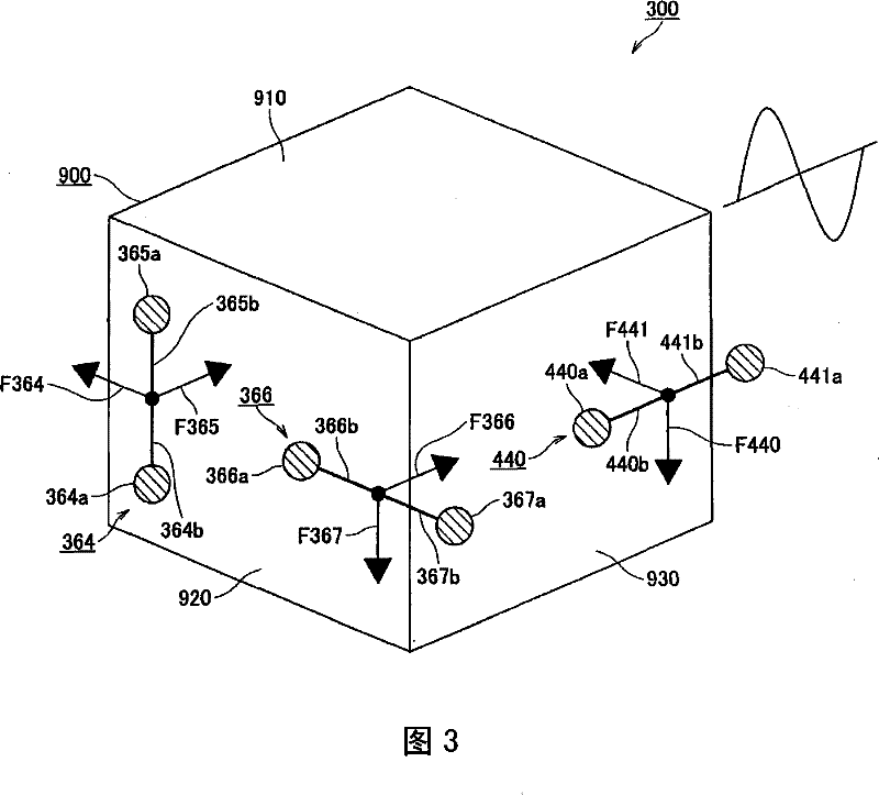
[0086] image 3 It is a schematic diagram showing an example of the vibration suppressing device 300 according to the third embodiment of the present invention.
[0087] Such as image 3 As shown, the vibration suppressing device 300 includes dynamic vibration absorbers 364, 366, and 440, and the vibration suppressing device 300 is installed on a box-shaped member 900 such as an engine or an electric motor.
[0088] Such as image 3 As shown, dynamic vibration absorbers 364 and 366 are provided on the surface 920 of the box-shaped member 900 of the vibration suppressing device 300 , and a dynamic vibration absorber 440 is provided on the surface 930 of the box-shaped member 900 .
[0089] here, Figure 4 yes means image 3 A schematic diagram of the dynamic vibration absorbers 364, 366 and 440 of FIG.
[0090] Such as Figure 4 As shown, the dynamic vibration absorber 364 is composed of hammer portions 364a, 365a and round rods 364b, 365b having elastic force. Also, the...
PUM
 Abstract
Description
Claims
Application Information
 - R&D
- Intellectual Property
- Life Sciences
- Materials
- Tech Scout
- Unparalleled Data Quality
- Higher Quality Content
- 60% Fewer Hallucinations
Browse by: Latest US Patents, China's latest patents, Technical Efficacy Thesaurus, Application Domain, Technology Topic, Popular Technical Reports.
© 2025 PatSnap. All rights reserved.Legal|Privacy policy|Modern Slavery Act Transparency Statement|Sitemap|About US| Contact US: help@patsnap.com