Conveyor with rigid carrying transmission plane and transmitting process thereof

A conveyor and rigid technology, applied in the field of conveyor and its transmission, can solve the problems of unfavorable market economic operation, large floor area, high cost, etc., achieve good use value and promotion value, low production and maintenance costs, and reduce The effect of transmission resistance

Inactive Publication Date: 2008-12-31
GUIYANG PUTIAN LOGISTICS TECH
View PDF0 Cites 8 Cited by
  • Summary
  • Abstract
  • Description
  • Claims
  • Application Information

AI Technical Summary

Problems solved by technology

[0002] At present, in the field of object conveying and sorting equipment technology, there are many existing equipment at home and abroad, but the conveying carrier generally adopts flexible conveying carriers such as conveyor belts, conveying rollers or conveying chains, and conveyors made of flexible conveying carriers It has the advantages of light weight and low production cost, and has been widely used in various industries; the existing conveyors generally adopt rollers or sprockets at both ends of the conveyor frame to drive the movement of the flexible conveying carrier. There is no supporting flexible conveying carrier device between the sprockets. This design limits the type and range of objects conveyed by the flexible conveying carrier. Cracking, compression deformation or making the upper and lower layers of flexible conveying carriers contact each other, so that in the field of object conveying, objects with heavy conveying quality are not conveyed by conveyors or must be conveyed by conveyors with strong conveying capacity and large volume. Conveyors with strong capacity and large volume will have disadvantages such as too wide, too large an area, and high cost, which is not conducive to the operation of the market economy

Method used


Image

  • Conveyor with rigid carrying transmission plane and transmitting process thereof
  • Conveyor with rigid carrying transmission plane and transmitting process thereof
  • Conveyor with rigid carrying transmission plane and transmitting process thereof

Examples


Embodiment Construction

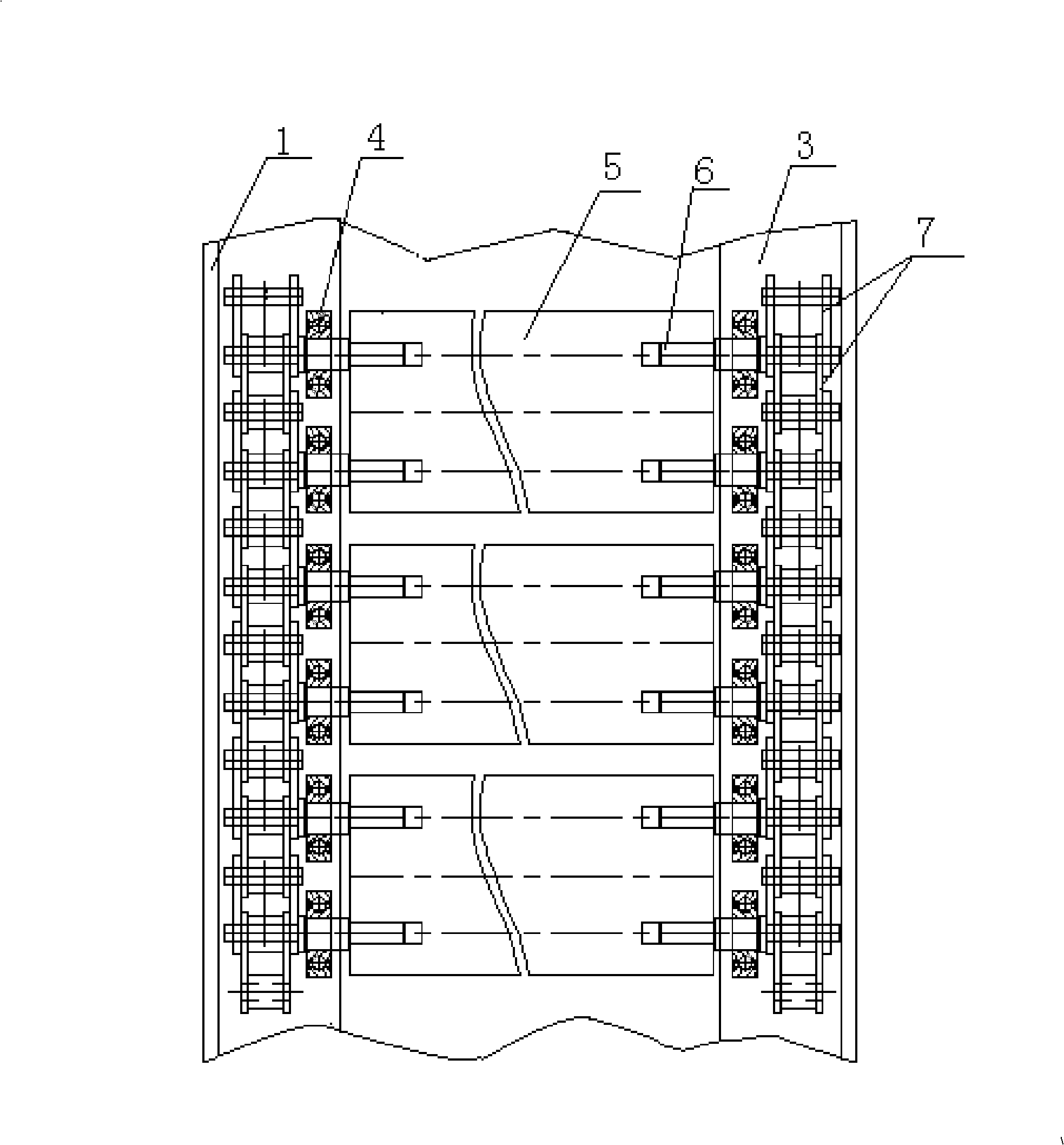
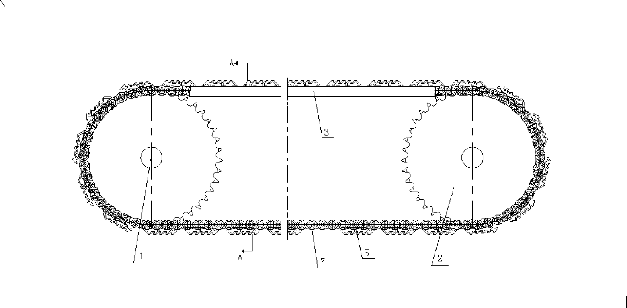
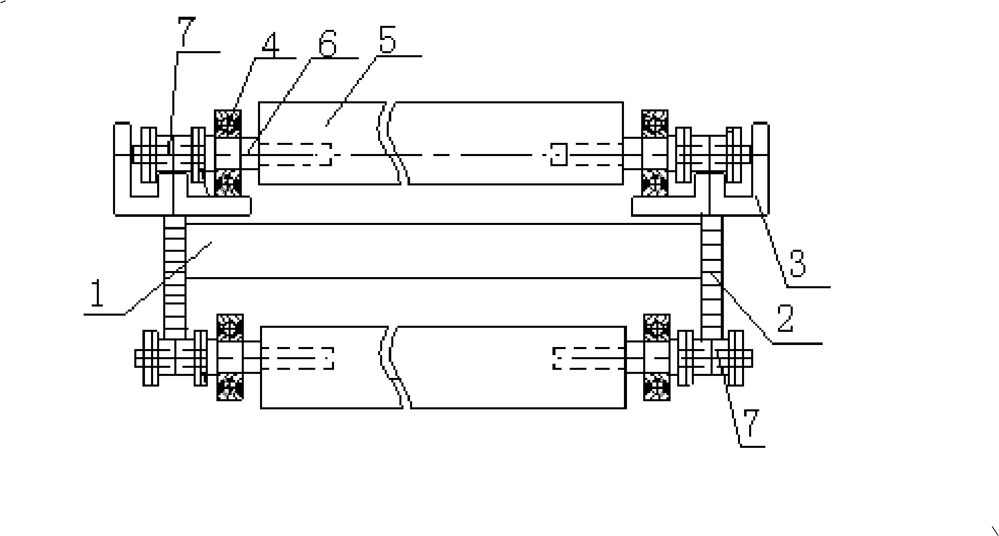
[0013] Embodiments of the present invention: When making a conveyor for conveying objects, a movable rigid carrier is used to convey objects, that is, rollers are installed on the rigid carrier as a carrier for transporting heavy objects, and multiple rigid carriers with rollers are connected by chains. Carriers are connected in series, and the rigid carriers connected in series are supported on the rigid track of the conveyor through their rollers. The chains are connected end to end, and the chains are driven by the sprockets set on the conveyor, and the chains drive the rigid carriers for circular motion. This rigid carrier conveyor is especially suitable for conveying bulky and heavy items.

[0014] When using the above method to specifically manufacture a conveyor whose transmission surface is a rigid carrier; figure 1 , figure 2 and image 3 As shown, it includes a frame 1, a sprocket 2 driven by a motor is installed at both ends of the frame 1, a chain 7 rotating wit...


PUM


Abstract

The invention discloses a transportation method of a conveyor with a transport surface being a rigid carrier. A mobile rigid carrier is adopted to transport goods, that is, roller wheels are installed on the rigid carrier as carriers transporting heavy goods; a plurality of rigid carriers with the roller wheels are mutually connected in serial by chains; the serially connected rigid carriers are supported on rigid tracks of the conveyor by the roller wheels; the chains are connected from beginning to end, and chain wheels installed on the conveyor drive the chain to move; simultaneously, the chains drive the rigid carrier to do circulatory movement. A rigid body with roller wheels is used as the transport carrier of a conveyor in the invention so that heavy goods with big volumes can be placed on the rigid carrier with a small volume; additionally, the device of the invention has simple structure and low manufacture cost, which can overcome certain disadvantages of the existing conveyor and has very good use value and popularization value.

Description

technical field [0001] The invention relates to a conveyor for conveying objects and a conveying method thereof, in particular to a conveyer whose conveying surface is a rigid carrier and a conveying method thereof, and belongs to the technical field of conveying object devices. Background technique [0002] At present, in the field of object conveying and sorting equipment technology, there are many existing equipment at home and abroad, but the conveying carrier generally adopts flexible conveying carriers such as conveyor belts, conveying rollers or conveying chains, and conveyors made of flexible conveying carriers It has the advantages of light weight and low production cost, and has been widely used in various industries; the existing conveyors generally adopt rollers or sprockets at both ends of the conveyor frame to drive the movement of the flexible conveying carrier. There is no supporting flexible conveying carrier device between the sprockets. This design limits ...

Claims


Application Information

Patent Timeline
IPC IPC(8): B65G17/06B65G17/30
Inventor 李燕海
Owner GUIYANG PUTIAN LOGISTICS TECH
Why Eureka
Try Eureka