
Shift control method for an automatic gearbox

A technology of automatic transmission and transmission, applied in the direction of electrical control, control device, engine control, etc., can solve the problems of shifting duration, shifting comfort, unfavorable shifting changes, etc., and achieve the effect of reducing wear

Inactive Publication Date: 2008-12-10
ZF FRIEDRICHSHAFEN AG
View PDF1 Cites 14 Cited by
  • Summary
  • Abstract
  • Description
  • Claims
  • Application Information

AI Technical Summary

Problems solved by technology

With regard to the control of the injection quantity, the injection quantity assigned to the idling torque is conventionally represented by a constant value, which in certain operating states, such as when shifting uphill with a high load, leads to a change in the duration of the shift, clutch wear and unfavorable shift changes in terms of shift comfort

Method used


Image

  • Shift control method for an automatic gearbox

Examples


Embodiment Construction

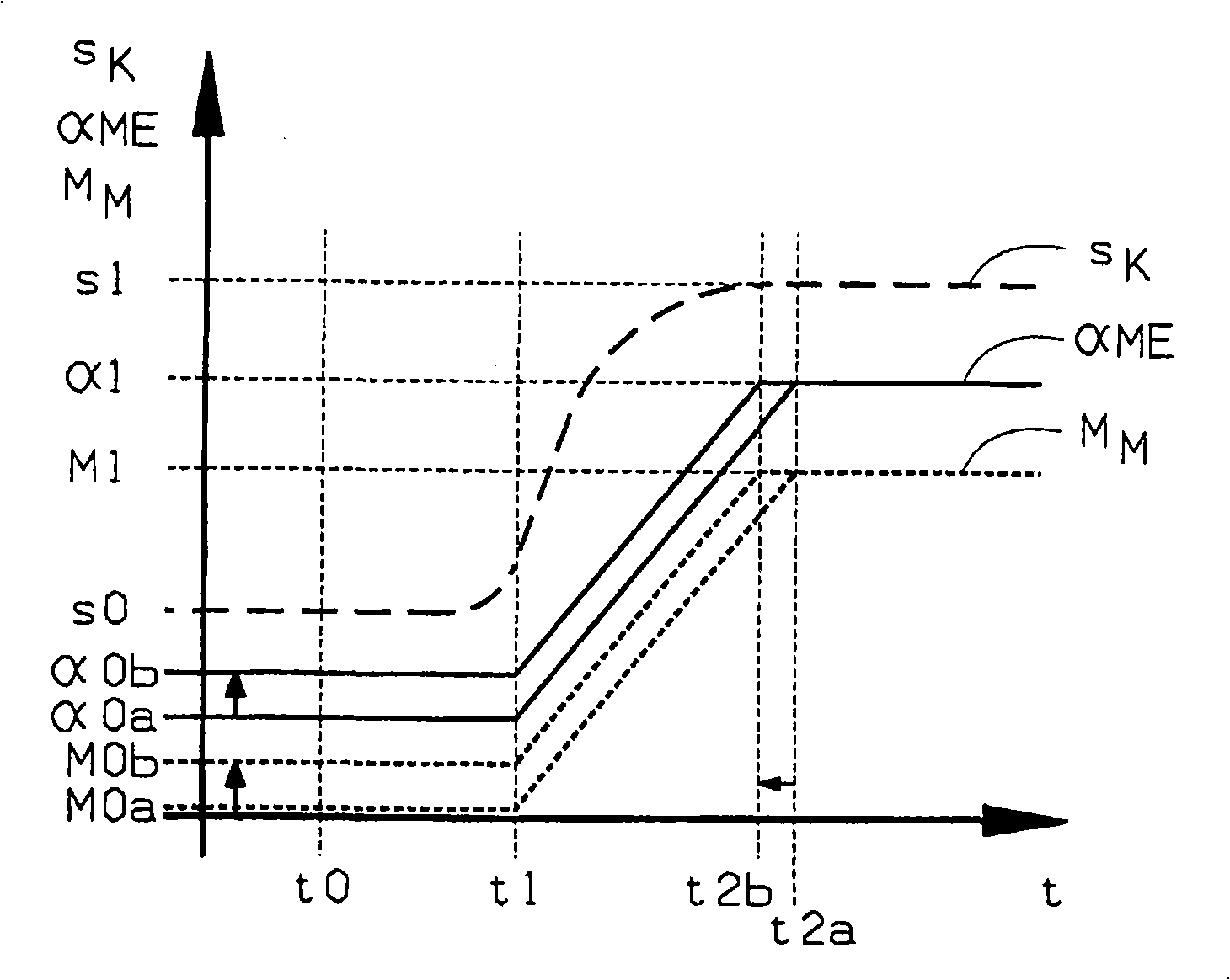
[0024] The time diagram shows, for example, the adjustment travel S of the motor clutch for the end of the shifting process with the opening of the motor clutch K , fuel injection quantity α M and the fuel injection quantity α of the transmission motor ME Control torque M M distribution over time t.

[0025] Engage the target gear and inject quantity α at time t0 ME In the normal case, it drops to the value α0a assigned to the idle torque M0a. Torque M of drive motor M Therefore, the value M0a is close to zero. The motor clutch is in position s0 when it is disengaged, that is to say fully disengaged. At time t1, the load composition of the drive motor begins to pass through the injection quantity α ME There is a ramp from the value α01 to the value α1 reached at time t2a. Torque M between t1 and t2a M Correspondingly, under the coordinated closing of the motor clutch at the same time (clutch stroke S K from position s0 to position s1), from value M0a to value M1. Th...


PUM


Abstract

During a gear shift from a gear under load to a target gear, the torque MM of the driving engine is set to an idling torque by a modification of the injection quantity aME before the gear under load is disengaged and to a load torque by a reverse modification of the injection quantity before the target gear is engaged. To allow the process to be better adapted to the respective operating conditions, at least one operating parameter that characterises the current operating condition of the motor vehicle and / or a shift parameter that characterises the designated gear shift is detected and evaluated at the start of the gear shift, and the injection quantity a0a of the driving motor that is assigned to the idling torque is variably adapted to the operating condition of the motor vehicle and / or the gear shift in accordance with the evaluated result.

Description

technical field [0001] The invention relates to a method for controlling the shifting of an automatic transmission of a motor vehicle, the input side of which is connected via a motor clutch in the form of an automatic friction clutch to a drive motor which is designed as an internal combustion engine with a controllable fuel injection system, Among them, in the process of shifting between the load gear and the target gear, before the load gear retreats, the torque of the transmission motor is adjusted to the idle torque by changing the fuel injection amount, and after the target gear is engaged, the torque of the transmission motor is changed to the idle torque in the opposite direction. The fuel injection quantity is adjusted to the load moment. Background technique [0002] The use of automatic transmissions in cars, both in the PKW sector and in the commercial vehicle sector, is increasing because of their high efficiency due to the shifting process that takes place auto...

Claims


Application Information

Patent Timeline
Patent Type & Authority Applications(China)
IPC IPC(8): F02D41/04B60W10/10B60W30/18
CPCB60W10/06B60W10/11B60W30/19B60W2510/0638B60W2510/0657B60W2510/0671B60W2530/16B60W2710/0616F02D41/023F02D2200/1002F02D2200/501F02D2200/602F02D2200/606F02D2200/702F02D2250/21F16H63/502F16H2063/506F02D41/04
Inventor 安杰尔科·韦森亚克
Owner ZF FRIEDRICHSHAFEN AG
Learn More