Electronic paper device, and its driving circuit and production method

A technology of driving circuit and manufacturing method, applied in the direction of cathode ray tube indicator, instrument, static indicator, etc., can solve the problems of huge cost and uneconomical efficiency, and achieve the effect of reducing cost and simple driving structure

Inactive Publication Date: 2008-12-03
GIGNO TECH CO LTD
View PDF0 Cites 2 Cited by
  • Summary
  • Abstract
  • Description
  • Claims
  • Application Information

AI Technical Summary

Problems solved by technology

[0005] Since each data line needs a recorder 12 to cooperate with the application, when the size of the display device becomes larger and larger, the cost caused by it will become larger and larger, and it will not be economical.

Method used


Image

  • Electronic paper device, and its driving circuit and production method
  • Electronic paper device, and its driving circuit and production method
  • Electronic paper device, and its driving circuit and production method

Examples


Embodiment Construction

[0065] In order to further explain the technical means and functions adopted by the present invention to achieve the intended purpose of the invention, the specific implementation methods, Structure, characteristic and effect thereof are as follows in detail.

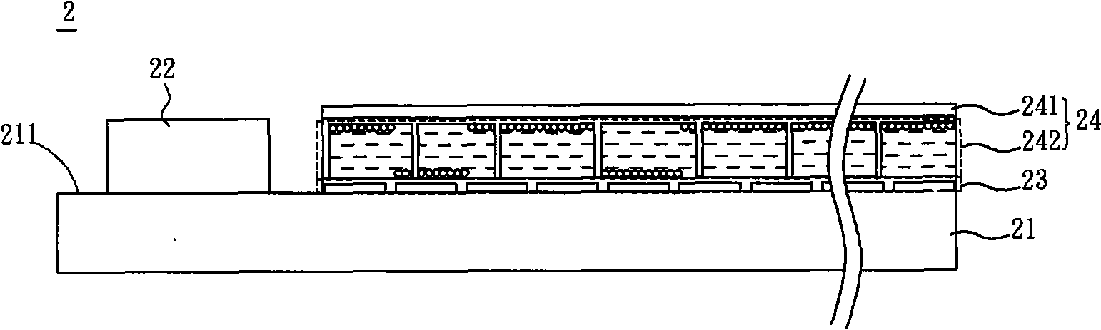
[0066] Please refer to figure 2 As shown, the electronic paper device 2 of the preferred embodiment of the present invention includes a substrate 21 , a driving circuit 22 , a pixel array 23 and an electronic paper 24 . Wherein, the driving circuit 22 and the pixel array 23 are arranged on a surface 211 of the substrate 21 , and the driving circuit 22 and the pixel array 23 are arranged adjacent to each other; the electronic paper 24 is arranged opposite to the pixel array 23 . The electronic paper 24 includes a pair of electrode units 241 and an electrophoretic substance unit 242 . The opposite electrode unit 241 is disposed opposite to the pixel array 23 , and the electrophoretic substance unit 242 is disposed betw...


PUM


Abstract

The invention relates to an electronic paper device, a driving circuit and a manufacturing method thereof. The driving circuit of the electronic paper device drives at least one picture element provided with a picture element switching element. The driving circuit comprises a displacement unit and a sample-and-hold unit. The displacement unit outputs a switching control signal. The sample-and-hold unit is provided with a sample-and-hold switching element and a sample-and-hold power storage element, wherein, the sample-and-hold switching element is respectively and electrically connected with the picture element switching element of the picture element and the displacement unit, and turns on or off based on the switching control signal; the sample-and-hold power storage element is electrically connected with the sample-and-hold switching element and the picture element switching element of the picture element. Moreover, the invention also discloses an electronic paper device and a manufacturing method thereof. The device, the driving circuit and the manufacturing method of the invention can achieve the aim of horizontal drive by simple driving framework.

Description

technical field [0001] The invention relates to an electronic paper device, a driving circuit and a manufacturing method thereof. Background technique [0002] Generally speaking, the method of driving an active matrix display device is to use a row (column) driver and a column (row) driver and cooperate with timing control to make the display device display image images. [0003] In the row driver, a sample-hold circuit is usually required to convert the sequential pixel data into parallel pixel data and input them into a pixel array. And because it needs to update the image data quickly, a structure similar to Static Random Access Memory (SRAM) is usually used in the sample and hold circuit to achieve the purpose of its fast operation. [0004] Please refer to figure 1 As shown, a general sample-and-hold circuit includes a shift register 11 and a recorder 12, wherein the recorder 12 is composed of four transistors. A pixel data is sent to the pixel array 13 through the ...

Claims


Application Information

Patent Timeline
IPC IPC(8): G09G5/00
Inventor 萨文志
Owner GIGNO TECH CO LTD
Why Eureka
Try Eureka